
Table of contents: Removal timing chains from camshafts… ↓ Removal and installation upper… ↓ Removal and installation the lower… ↓
1. Timing chain installation details are shown in the illustrations.
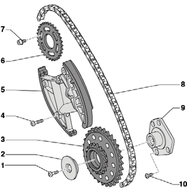
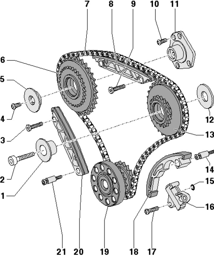
9.1a. Installation details of the upper left timing chain of BUG/BUN engines:
1, 4 - Bolt, subject to replacement, 5 Nm, then tighten to an angle of 90°;
2 - Sprocket support washer 3;
3 - Drive sprocket of the left cylinder head shafts;
5 - Chain tensioner 8;
6 - Driven sprocket of the left cylinder head shafts;
7 - Bolt, 23 Nm;
8 - Left upper timing chain;
9 - Sprocket carrier bracket 6;
10 - Bolt, 9 Nm.
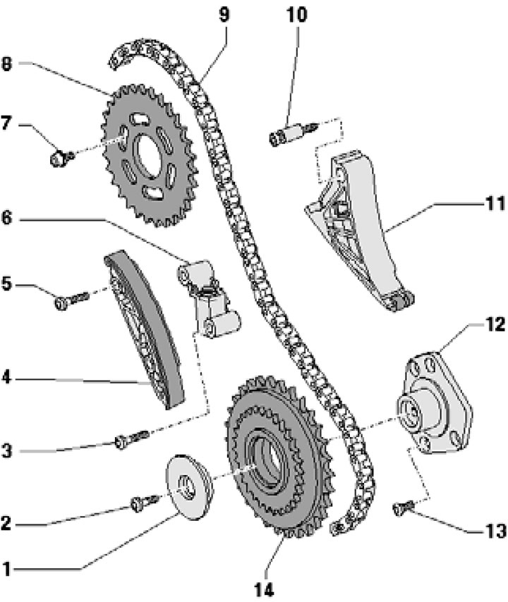
9.1b. Installation details of the upper left timing chain of CASA/CASB, CATA and CCMA engines:
1 - Sprocket support washer 14;
2, 13 - Bolt;
3, 5 - Bolt, subject to replacement, 5 Nm, then tighten to an angle of 90°;
4 - Guide bar;
6 - Chain tensioner 9;
7 - Bolt, 23 Nm;
8 - Driven sprocket of the left cylinder head shaft drive;
9 - Left upper timing chain;
10 - Bolt with sleeve, subject to replacement, 5 Nm, then tighten to an angle of 90°;
11 - Tensioner bar 6;
12 - Sprocket carrier bracket 14;
14 - Drive sprocket of the left cylinder head shafts.
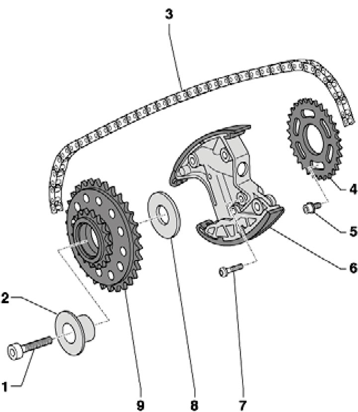
9.1.c Installation details of the upper right timing chain of BTR, BUG/BUN, CASA/CASB, CATA, CCFA/CCFC and CCMA engines:
1 - 3.0 TDI engines: bolt, 45 Nm;
1 - 4.2 TDI engines: bolt, to be replaced, 20 Nm, then tighten to an angle of 45°;
2 - Sprocket bearing support 9;
3 - Right upper timing chain;
4 - Driven sprocket of the right cylinder head shafts;
5 - Bolt, 23 Nm;
6 - Chain tensioner 3;
7 - Bolt, to be replaced, 5 Nm, then tighten to an angle of 90°;
8 - Sprocket support washer 9;
9 - Drive sprocket of the right cylinder head shafts.
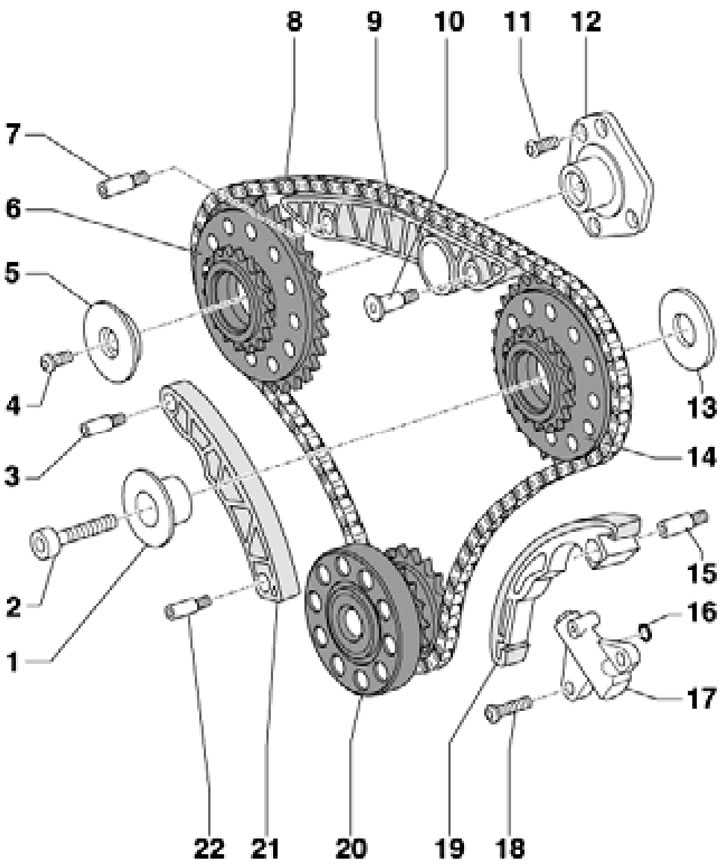
9.1d. Details of the installation of the lower timing chain of BUG/BUN engines:
1 - Sprocket bearing support 14;
2 - Bolt, 45 Nm;
3 - Mounting pin, 9 Nm, tightened with thread sealant;
4 - Bolt, to be replaced, 5 Nm, then tighten to an angle of 90°;
5 - Sprocket support washer 6;
6 - Drive sprocket of the left cylinder head shafts;
7, 10, 15 - Mounting pin, 12 Nm, tightened with thread sealant;
8 - Lower timing chain;
9, 21 - Guide bar;
11 - Bolt, 9 Nm;
12 - Sprocket support bracket 6;
13 - Sprocket support washer 14;
14 - Drive sprocket of the right cylinder head shafts;
16 - Sealing ring, must be replaced;
17 - Chain tensioner 8;
18 - Bolt, 12 Nm;
19 - Tensioner bar 17;
20 - Crankshaft;
22 - Mounting pin, 9 Nm.
9.1e. Installation details of the lower timing chain for BTR, CASA/CASB, SATA and CCMA engines:
1 - Sprocket bearing support 13;
2 - 3.0 TDI engines: bolt, 45 Nm;
2 - 4.2 TDI engines: bolt, to be replaced, 20 Nm, then tighten to an angle of 45°;
3, 4, 9, 10 - Bolt, subject to replacement, 5 Nm, then tighten to an angle of 90°;
5 - Sprocket support washer 6;
6 - Drive sprocket of the left cylinder head shafts;
7 - Lower timing chain;
8, 20 - Guide bar;
11 - Sprocket carrier bracket 6;
12 - Sprocket support washer 13;
13 - Drive sprocket of the right cylinder head shafts;
14, 21 - 3.0 TDI engines: mounting pin, 12 Nm, tightened with thread sealant;
14, 21 - 4.2 TDI engines: bolt with sleeve, must be replaced, 5 Nm, then tighten to an angle of 90°;
15 - Sealing ring, must be replaced;
16 - Chain tensioner 7;
17 - 3.0 TDI engines: bolt, 12 Nm;
17 - 4.2 TDI engines: bolt, must be replaced, 5 Nm, then tighten to an angle of 90°;
18 - Tensioner bar 16;
19 - Crankshaft.
Removal timing chains from camshafts only
Note: After performing work on only one cylinder head, the timing phases only need to be adjusted on that cylinder head.
Note: For clarity, illustrations are shown from the rear of the engine with the engine removed.
Caution: When loosening the fasteners of the timing drive components, seal the openings in the timing case with a cloth to prevent fasteners and small parts from falling into the engine. Otherwise, the engine may be irreversibly damaged.
2. The power unit cannot be removed.
3. Drain the coolant (see chapter 3).
4. Remove the primary catalytic converter (see Chapter 4).
5. Remove the vacuum pump (see chapter 8).
6. Remove the rear right coolant pipe, and on models with CASA/CASB engines - also the rear left coolant pipe (see Chapter 3).
7. Remove the upper timing chain covers (see Section 8).
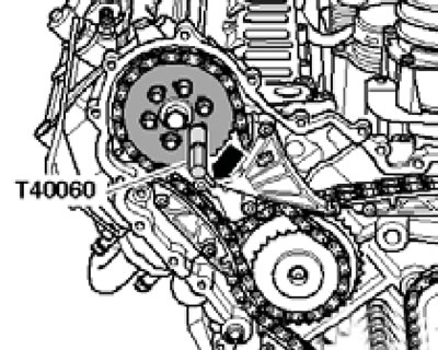
8. Using the T40058 tool, turn the crankshaft clockwise to the TDC position (see illustrations 4.73a-b).
9. To check the TDC position, you will need the T40060 tool (see illustration).
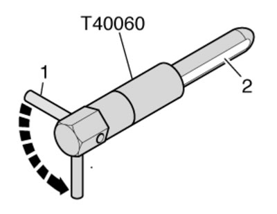
9.9. Device T40060.
It has a chamfer (2) that simplifies the installation of the device when the holes in the camshaft and cylinder head do not exactly match. The tool is first inserted so that the pin (1) is positioned perpendicular to the imaginary line between the tool and the center of the camshaft. To ensure the correct TDC position, the pin (1) must then be turned 90° (arrow) so that it is on the imaginary line between the device and the center of the camshaft.
10. Check that the camshafts are at TDC by locking them with tool T40060 as described in paragraph 9 (see illustrations).
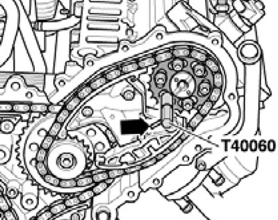
9.10a. Checking the position of the BMT shafts of the right cylinder head.
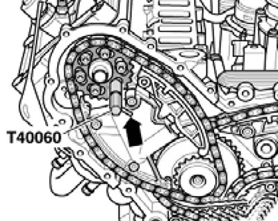
9.10b. Checking the TDC position of the left cylinder head shafts (bUG/BUN engines).
9.10 p. Checking the TDC position of the left cylinder head shafts (cASA/CASB engines, SATA, SSMA).
11. Place a cloth under the upper section of the oil pan to collect any leaking oil. Unscrew the plug from the upper section of the oil pan and through the resulting service hole, screw the locking pin No. 3242 into the crankshaft locking hole (with a force of 20 Nm), - see illustration.
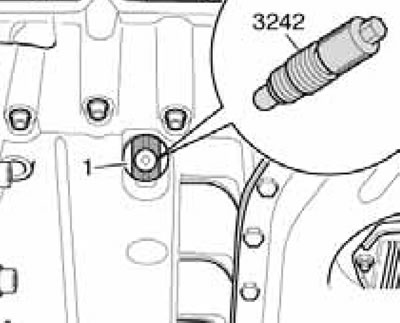
9.11. The locking hole in the crankshaft, visible through the service hole in the upper section of the oil pan.
If necessary, rotate the crankshaft forward/backward slightly to completely align the bore centers.
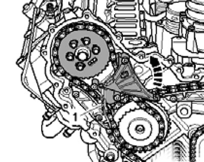
12. Wrap the 3.3mm drill bit with electrical tape to prevent cutting yourself on it. On BUG/BUN engines, press the left upper timing chain tensioner bar in the direction of the arrow (see illustration 9.12a) and lock the tensioner with the prepared drill (1).
9.12a. Upper left timing chain tensioner lock (bUG/BUN engines).
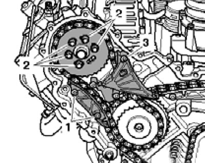
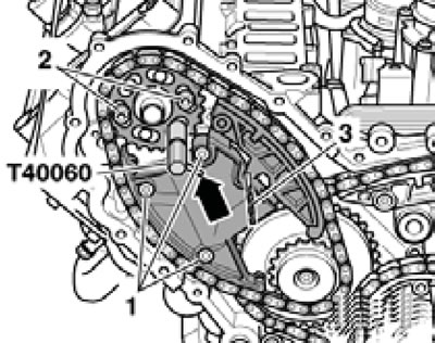
Remove the bolts (1 in illustration 9.12b) tensioner bars and bolts (2) of the camshaft sprocket.
9.12b. Bolts of the tension bar (1) and sprocket (2) of the left camshaft of BUG/BUN engines.
Remove the sprocket and tensioner.
13. On CASA/CASB engines, press the left upper timing chain tensioner bar in the direction of the arrow (see illustration 9.13a) and lock the tensioner with the prepared drill (1).
9.13a. Upper left timing chain tensioner lock (cASA/CASB engines, SATA, SSMA).
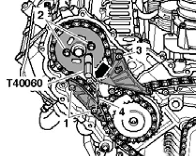
Remove the bolt (3 in illustration 9.13b) tensioner bars and remove it.
9.13b. Bolts of the tension bar (3), guide bar (1) and left camshaft sprocket (2) of CASA/CASB, CATA, CCMA engines.
Remove the bolts (1) of the guide plate and the bolts (2) of the camshaft sprocket. Remove the sprocket and guide bar.
14. Press the right upper timing chain tensioner bar in the direction of the arrow (see illustration 9.14a) and lock the tensioner with the prepared drill (1).
9.14a. Upper right timing chain tensioner lock.
Remove the bolts (1 in illustration 9.14b) tensioner bars and bolts (2 and 3) of the camshaft sprocket.
9.14b. Tensioner bolts (1) and right camshaft sprockets (2 and 3).
Remove the sprocket and tensioner.
15. Before installation, make sure that the crankshaft is locked at TDC with locking pin No. 3242 (see illustration 9.11).
9.15. Turning the camshaft.
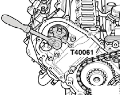
The lower timing chain must be installed. Make sure that the camshafts of both cylinder heads are also at TDC by inserting the T40060 tool into their holes (see paragraphs 9-10). If it is not possible to install these devices, slightly turn the corresponding shaft using the T40061 adapter (see illustration), secured with standard sprocket mounting bolts.
Caution: When turning the camshafts, the crankshaft must not be in the position corresponding to the TDC of any piston. Otherwise, valves and pistons may be damaged. After checking, remove the T40060 tools and do not turn the shafts any further.
16. On BUG/BUN engines, install the upper left timing chain together with the camshaft sprocket and tensioner. The centers of the sprocket's oblong holes must be located above the tapered holes in the camshaft. Tighten the bolts (1 in the illustration) tensioner and screw in the two bolts (2) of the sprocket.
9.16. Tensioning the left upper timing chain (bUG/BUN engines).
Do not tighten the sprocket bolts completely - it should be possible to rotate the sprocket on the shaft without axial displacement. Lock the shaft with tool T40060 (see paragraph 9) and release the chain tensioner by pulling out the drill (3).
17. On CASA/CASB engines, install the upper left timing chain together with the camshaft sprocket, guide rail and tensioner rail. The centers of the sprocket's oblong holes must be located above the tapered holes in the camshaft. Tighten the bolts (1 and 3 in the illustration) tension and guide strips and screw in two bolts (2) of the sprocket.
9.17. Tensioning the left upper timing chain (cASA/CASB engines, SATA, SSMA).
Do not tighten the sprocket bolts completely - it should be possible to rotate the sprocket on the shaft without axial displacement. Lock the shaft with tool T40060 (see paragraph 9) and release the chain tensioner by pulling out the drill (4).
18. Install the upper right timing chain together with the camshaft sprocket and tensioner. The centers of the sprocket's oblong holes must be located above the tapered holes in the camshaft. Tighten the bolts (1 in the illustration) tensioner and screw in the two bolts (2) of the sprocket.
9.18. Tensioning the right upper timing chain.
Do not tighten the sprocket bolts completely - it should be possible to rotate the sprocket on the shaft without axial displacement. Lock the shaft with tool T40060 (see paragraph 9) and release the chain tensioner by pulling out the drill (3).
19. Using a torque wrench and adapter T40062, apply a force of 30 Nm to the driven sprocket of the right cylinder head shaft drive (bUG/BUN engines) or 20 Nm (cASA/CASB engines) in the direction of the arrow. Maintaining this force, tighten the bolts (1 and 2 in illustration 9.19a).
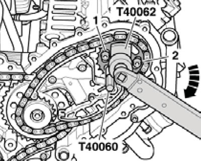
9.19a. Tightening the right sprocket bolts.
Then remove the T40062 adapter with the T40060 tool and tighten the remaining sprocket mounting bolts. Tighten the left sprocket mounting bolts in the same manner (see illustrations 9.19b-c), creating a preload of 15 Nm.
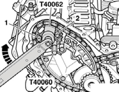
9.19b. Tightening the left sprocket bolts (bUG/BUN engines).
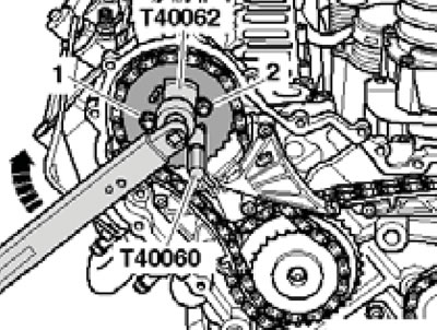
9.19s. Tightening the left sprocket bolts (cASA/CASB engines, SATA, SSMA).
20. Unscrew locking pin No. 3242 (see illustration 9.11) and check the timing adjustment as described below.
21. Turn the crankshaft clockwise two revolutions, exactly to the next TDC position, and again lock the crankshaft at TDC with locking pin #3242, tightening it to a torque of 20 Nm. If the crankshaft has turned past TDC even slightly, turn it approximately two more revolutions to a position approximately 10° before TDC, and then carefully turn it exactly to TDC.
22. Make sure that all camshafts are at TDC: it should be possible to lock them with T40060 tools (see paragraphs 9-10). If the camshafts cannot be locked, adjust the timing as described below.
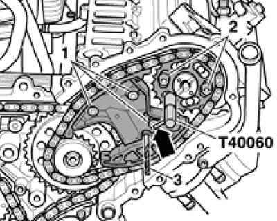
23. Loosen all the bolts securing the sprocket of the corresponding camshaft by approximately one turn, install the adapter T40061 on the bolts, slightly turn the shaft and insert the device T40060 (see illustration), as described in paragraph 9.
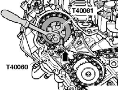
9.23. Timing phase adjustment (using the example of the left cylinder head of CASA/CASB, SATA, CCMA engines).
Holding the shaft in this position, tighten the sprocket mounting bolts to 5 Nm. Then remove adapter T40061 with tool T40060 and finally tighten the bolts to 23 Nm. Repeat this procedure on the other cylinder head, if necessary.
24. Unscrew locking pin No. 3242 and check the timing adjustment again (go to paragraph 21).
25. Tighten the service hole plug in the upper section of the oil pan with a new gasket to 35 Nm.
26. Install the timing chain covers (see section 8).
Removal and installation upper timing chains
Caution: Do not rotate the crankshaft or camshafts when the timing belt is not fully installed.
Note: If you intend to reuse the chain, mark the front side of the chain with paint so that you can install the chain in the same way later (movement of the chain used in the opposite direction is not allowed).
27. Remove the timing chain covers (see section 8).
28. Attach the special key T40049 to the rear side of the crankshaft using two old drive disk mounting bolts and turn the crankshaft in the direction of the arrow to the TDC position (see illustrations).
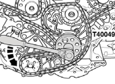
9.28a. Tool T40049 on the rear side of the crankshaft (bUG/BUN engines).
9.28b. Tool T40049 on the rear side of the crankshaft (cASA/CASB engines, SATA, SSMA).
Lock the shafts at TDC as described in paragraphs 9-11.
29. Wrap a 3.3mm drill bit with electrical tape to prevent cutting yourself on it. On BUG/BUN engines, press the left upper timing chain tensioner bar in the direction of the arrow (see illustration 9.12a) and lock the tensioner with the prepared drill (1). Remove the T40060 fixture from both shafts. Unscrew the bolts (1 in illustration 9.12b) tensioner bars and bolts (2) of the camshaft sprocket. Remove the sprocket, tensioner and left chain.
30. On CASA/CASB engines, press the left upper timing chain tensioner bar in the direction of the arrow (see illustration 9.13a) and lock the tensioner with the prepared drill (1). Remove the T40060 tool from both shafts. Unscrew the bolt (3 in illustration 9.13b) tensioner bar and remove it. Unscrew the bolts (1) of the guide bar and the bolts (2) of the camshaft sprocket. Remove the sprocket, guide bar and left chain.
31. Press the right upper timing chain tensioner bar in the direction of the arrow (see illustration 9.14a) and lock the tensioner with the prepared drill (1). Mark the front side of the chain with paint so that you can install it in the same way later (movement of the chain used in the opposite direction is not allowed). Remove the bolts (1 in illustration 9.14b) tensioner bars and bolts (2 and 3) of the camshaft sprocket. Remove the sprocket, tensioner and right chain.
32. Perform the steps described in paragraphs 15-26. When doing this, install the chains together with the sprockets and ensure that the chains used are installed as before (according to the marks).
Removal and installation the lower timing chain
Note: If you intend to reuse the chain, mark the front side of the chain with paint so that you can install the chain in the same way later (movement of the chain used in the opposite direction is not allowed).
33. Remove the upper timing chains (see subsection above) and the auxiliary drive chain (see Section 10).
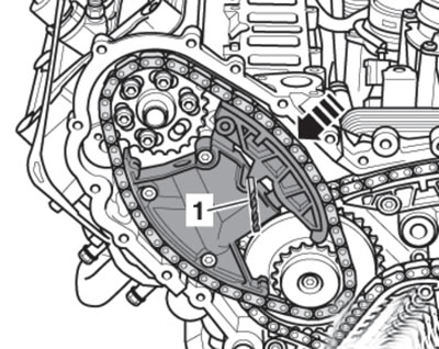
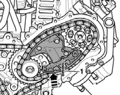
34. On BUG/BUN engines, wrap the 3.3mm drill bit with electrical tape to prevent cutting yourself on it. Press the tensioner bar in the direction of the arrow (see illustration) and lock the tensioner by inserting the prepared drill (4).
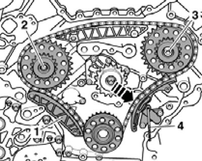
9.34. Removing the lower timing chain of BUG/BUN engines.
Unscrew the bolts (2 and 3) and remove the sprockets together with the chain and guide bar (1).
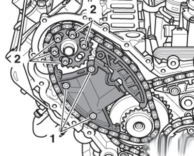
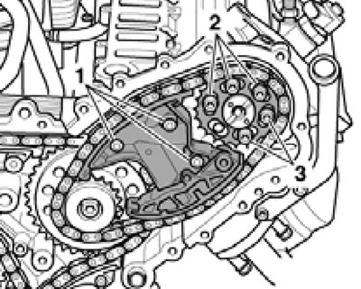
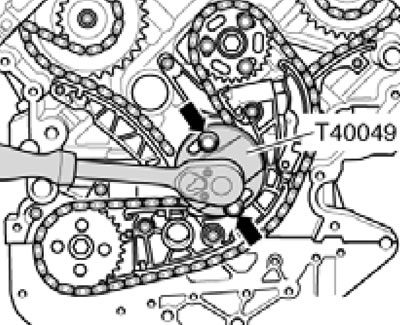
35. On CASA/CASB engines, press the tensioner bar in the direction of the arrow (see illustration) and lock the tensioner by inserting the T40071 tool.
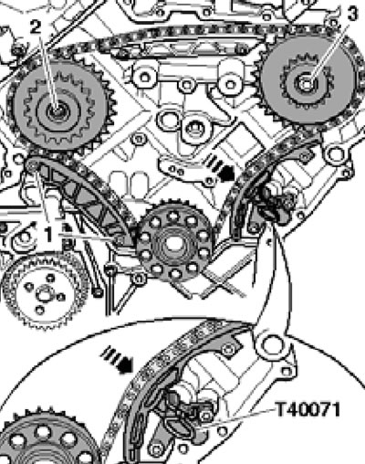
9.35. Removing the lower timing chain of CASA/CASB engines.
Unscrew the bolts (1) and remove the guide bar. Then unscrew the bolts (2 and 3) and remove the sprockets together with the chain. Installation is carried out in reverse order. On BUG/BUN engines, please note the following features.
36. Before installation, make sure that the crankshaft is locked at TDC with locking pin No. 3242 (see illustration 9.11). First install the left sprocket (2 in illustration 9.34), then the guide bar (1) with the chain installed, and then the right sprocket (3). After this, press the tensioner bar in the direction of the arrow and pull out the drill (4) to tighten the chain.
(The original article is available on the online resource «Audimanual.ru»)