
Table of contents: Accessory drive chain ↓ Balance shaft ↓
1. The installation details of the balance shaft and accessory drive chain are shown in the illustrations.
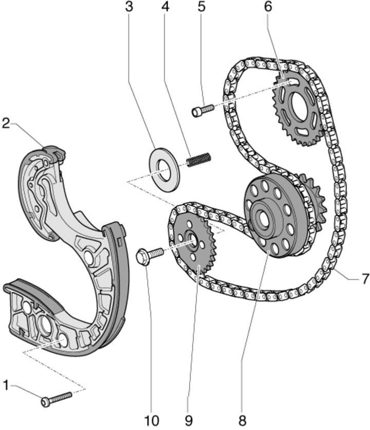
10.1a. Details of the installation of the drive chain of auxiliary units of BUG/BUN engines:
1 - Bolt, 9 Nm;
2 - Chain tensioner with guide bar;
3 - Thrust washer;
4 - Spring;
5 - Bolt, 23 Nm;
6 - Balance shaft sprocket, the side with the letters faces AT;
7 - Auxiliary drive chain;
8 - Crankshaft;
9 - Oil pump sprocket;
10 - Bolt.
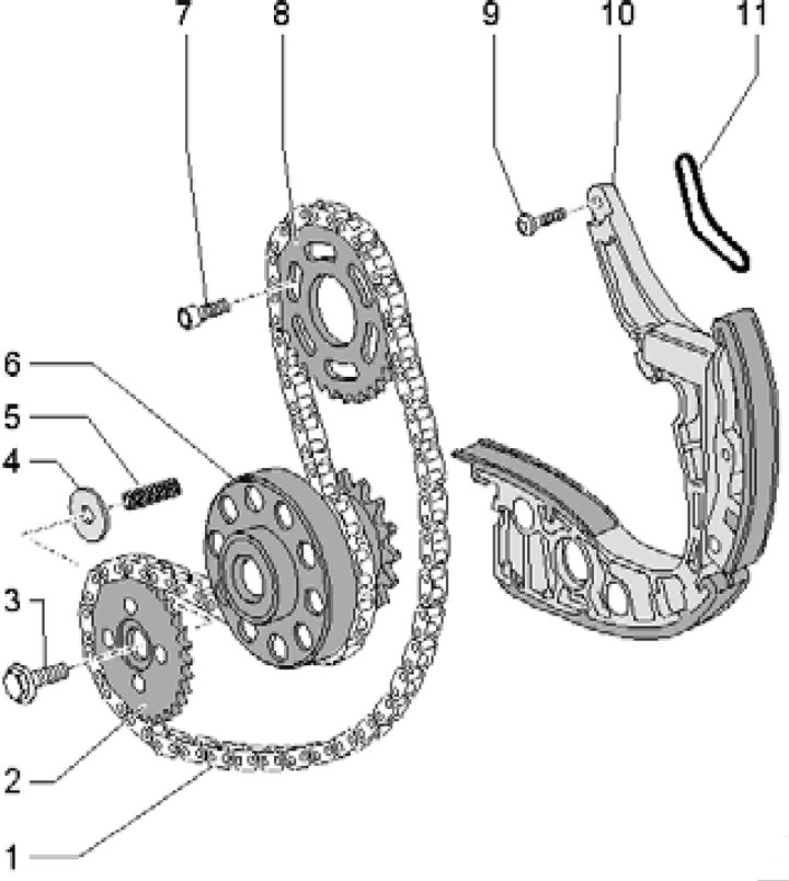
10.1b. Installation details of the auxiliary drive chain for CASA/CASB, CATA, CCMA engines:
1 - Auxiliary drive chain;
2 - Oil pump sprocket, lettered side facing the engine;
3 - Bolt;
4 - Thrust washer;
5 - Spring;
6 - Crankshaft;
7 - Bolt, 23 Nm;
8 - Balance shaft sprocket, the side with the letters faces AT;
9 - Bolt, 9 Nm;
10 - Chain tensioner with guide bar;
11 - Gasket, subject to replacement.
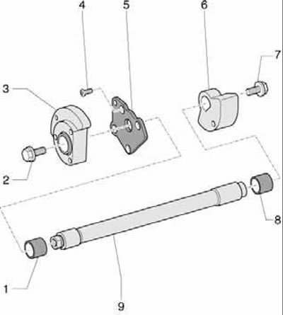
10.1c. Balance shaft installation details:
1, 8 - Bearing bushing;
2, 7 - Bolt, 60 Nm; hold while loosening/tightening with locking pin No. 3359 for fuel injection pump;
3 - Balancer on the AT side;
4 - Bolt, 9 Nm, tighten with thread sealant;
5 Carrier plate;
6 - Balance beam on the pulley side;
9 - Balance shaft.
Accessory drive chain
Note: If you intend to reuse the chain, mark the front side of the chain with paint so that you can install the chain in the same way later (movement of the chain used in the opposite direction is not allowed).
2. Remove the timing chain covers (see Section 8).
3. Secure the special key T40049 to the rear side of the crankshaft using two old drive disk mounting bolts (see illustration 9.28).
4. Fix the crankshaft at TDC as described in paragraph 11 Section 9.
5. Lock the balance shaft at the rear of the engine with the locking pin No. 3359 for the fuel injection pump and loosen the bolts (arrows in illustrations) balance shaft sprockets.
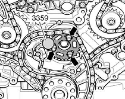
10.5. Fixing the balance shaft sprocket and its fastening.
Wrap a 3.3mm drill bit with electrical tape to prevent cutting yourself.
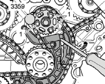
6. On BUG/BUN engines, press the tensioner bar in the direction of the arrow (see illustration) and lock the tensioner with the prepared drill (1).
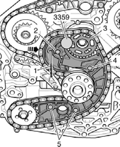
10.6. Removing the auxiliary chain (bUG/BUN engines).
Remove the bolts (2, 4 and 5) and remove the tensioner, balance shaft sprocket (3) and chain.
7. On CASA/CASB engines, press the tensioner bar in the direction of the arrow (see illustration) and lock the tensioner with the prepared drill (4).
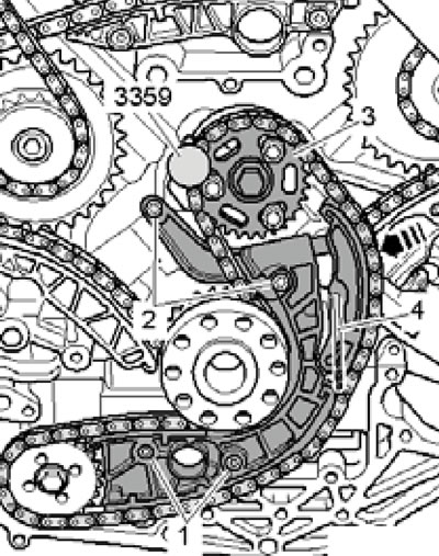
10.7. Removing the auxiliary chain (cASA/CASB engines).
Unscrew the bolts (1 and 2) and remove the tensioner, balance shaft sprocket (3) and chain.
8. Before installation, make sure that the crankshaft is locked at TDC with locking pin No. 3242 (see illustration 9.11).
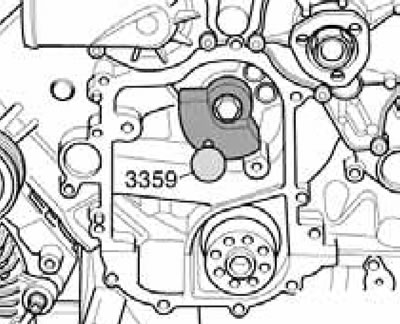
9. Lock the balance shaft on the rear side of the engine with the locking pin No. 3359 for the fuel injection pump (see illustration).
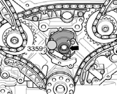
10.9. Fixing the balance shaft.
10. Install the chain tensioner and balance shaft sprocket. The centers of the sprocket's oblong holes must be located above the tapered holes in the balance shaft. Tighten the tensioner mounting bolts (see illustration 10.6 or 10.7).
11. Tighten the balance shaft sprocket bolts until it can still rotate on the shaft without axial displacement. Pull the drill out to release the tensioner.
12. Use a screwdriver to press the tensioner bar in the direction of the arrow (see illustrations) and at the same time tighten the bolts (1) securing the sprocket.
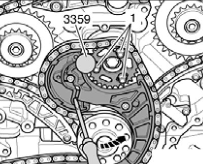
10.12a. Tightening the balance shaft sprocket mounting bolts (bUG/BUN engines).
10.12b. Tightening the balance shaft sprocket mounting bolts (cASA/CASB engines).
Remove locking pin No. 3359 from the balance shaft.
13. Install the timing chain covers.
Balance shaft
14. Remove the accessory drive chain (see subsection above).
15. Remove the front sealing flange (see Section 7).
16. Lock the balance shaft on the front side of the engine with the locking pin NS3359 for the fuel injection pump (see illustration).
10.16. Removing the front balancer.
Unscrew the bolt and remove the front balancer.
17. Lock the balance shaft on the rear side of the engine with locking pin No. 3359 for the fuel injection pump (see illustration 10.9). Remove the bolt (arrow) and the rear balancer.
18. Remove the bolts (see illustration) and remove the balance shaft carrier plate.
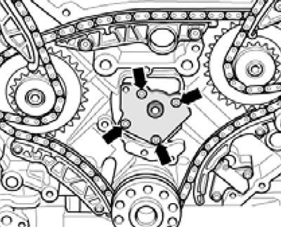
10.18. Balance shaft carrier plate mounting bolts.
Pull the balance shaft out of the cylinder block.
19. Installation is carried out in reverse order. Before installation, make sure that the crankshaft is locked at TDC with locking pin No. 3242 (see illustration 9.11). Finally, fill the engine oil (see Section 6 of Chapter 1).