
Note: If the removed parts are to be reused, arrange them so that they will be in their original locations and orientations when reinstalled.
Caution: Metal shavings or large quantities of small metal particles found during engine rebuild may indicate damage to the crankshaft and connecting rod bearings. To prevent further damage, thoroughly clean the oil passages and replace the oil injectors, oil cooler and oil filter.
1. The crankshaft installation details are shown in the illustration.
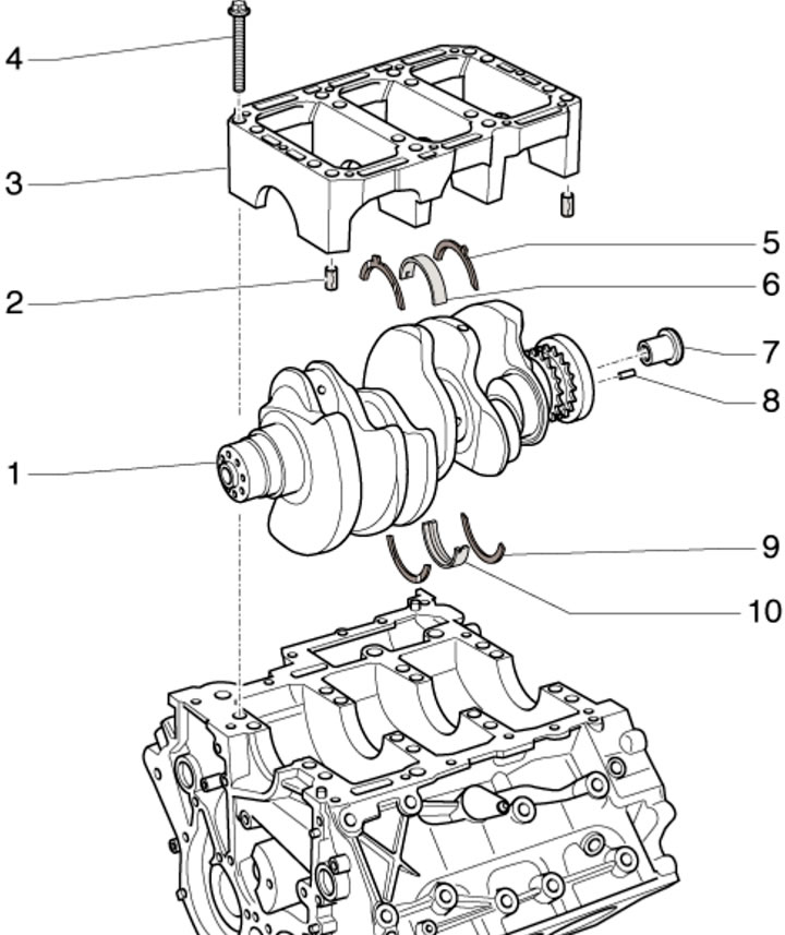
14.1. Crankshaft installation details:
1 - Crankshaft;
2 - Centering bushings of bed 3, 2 pcs., inserted into the cylinder block;
3 - Shaft bed 1;
4 - Bed mounting bolt 3 (see illustration 14.2), subject to replacement;
5, 9 - Thrust washers, installed only on bearing #3, oil grooves facing outward;
6 - Lower main bearing shell (in bed 3), without oil groove;
7 - Torque converter centering sleeve, in the center of the rear end of the crankshaft;
8 - Centering sleeve of the drive disk, inserted into the crankshaft;
10 - Upper main bearing shell (in the cylinder block), with oil groove.
2. After removing the crankshaft bed, use new bolts to secure it. Before installing the bed, make sure that there are two centering pins in the cylinder block. Tighten the bed mounting bolts in sequence (1-16 in the illustration) in three approaches: first with a force of 30 Nm, then with a force of 50 Nm, and finally pull to an angle of 90°.
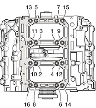
14.2. Sequence of tightening the crankshaft bed fasteners.
3. The main bearing shells are marked by thickness with colored dots. The inserts of the required thickness are installed at the factory. Liners worn down to the nickel layer should be replaced. You can determine which color dotted bearing to use by looking at the letters: G - yellow, B - blue, R - red. The letters for selecting the upper bearings are located on the cylinder block, next to the corresponding bearing (see illustration 14.3a), and the letters for selecting the lower liners are located on the crankshaft cheek (see illustration 14.3b).
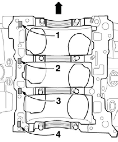
14.3a. Marking for selecting upper main bearing shells (arrow - to the pulley).
14.3b. Marking for selecting lower main bearing shells.
The number "1" before the sequence of letters indicates the starting point: from bearing No. 1.
4. The parts of the connecting rod and piston group are shown in the illustration.
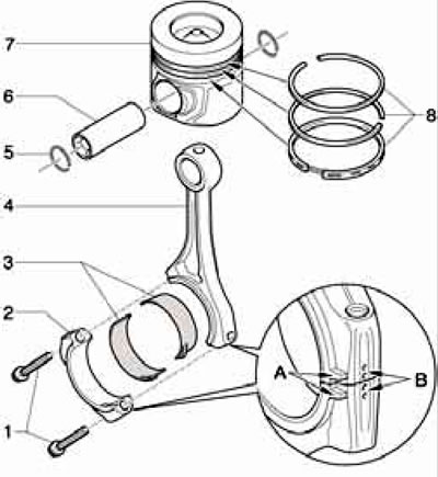
14.4. Connecting rod and piston group parts:
1 - Cover fastening bolts 2, subject to replacement, tighten with lubricated threads and mating surface: 30 Nm, then tighten to an angle of 90°;
2 - Connecting rod bearing cap, installed only in one position and only on a pair of connecting rods; with the mark "B" indicating belonging to the cylinder and the protrusion "A" on the timing drive side;
3 - Connecting rod bearing shells;
4 - Connecting rod with mark "B" and protrusion "A" (see point 2), can only be replaced as a complete assembly with cover 2;
5 - Retaining ring, 2 pcs., subject to replacement;
6 - Piston pin, to facilitate removal, heat the piston to 60°C;
7 - Piston, arrow should point towards the crankshaft pulley;
8 - Piston rings are installed at 120° intervals between locks, the "TOP" mark should face the piston bottom.
Liners worn down to the nickel layer should be replaced.
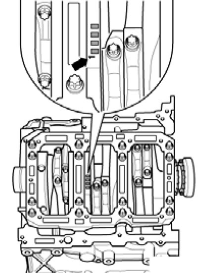
5. Oil nozzles (2 in the illustration) to cool the pistons, they are fastened with bolts (1) with a force of 9 Nm.
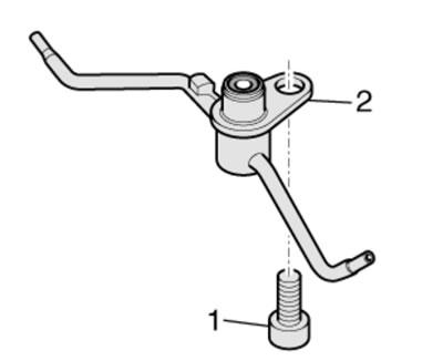
14.5. Bolt (1) for fastening the oil nozzle (2) for cooling the piston.
6. The wider areas on the connecting rod bearing caps should face the nearest main bearing (see illustration).
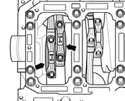
14.6. Orientation of connecting rods in a pair.
7. When installing new parts of the connecting rod and piston group or a "short" cylinder block, a new cylinder head gasket should be selected (separately for each head). The thickness of the gasket is determined based on the maximum protrusion of any of the pistons in a given cylinder bank when that piston is at TDC. Depending on the maximum protrusion of the pistons, a gasket with one, two, or three holes is used (1 in illustration 11.22), see Specifications.