
Table of contents: Removal and installation the oil pump ↓ Removal and installation the upper… ↓ Removal and installation the oil… ↓ Removal and installation the oil… ↓ Removal and installation the oil… ↓ Removal and installation the PCV… ↓ Removal and installation the… ↓ Removal and installation the… ↓ Removal and installation of the "F1"… ↓ Removal and installation of the "F1"… ↓
1. The installation details of the lubrication system components are shown in the illustrations.
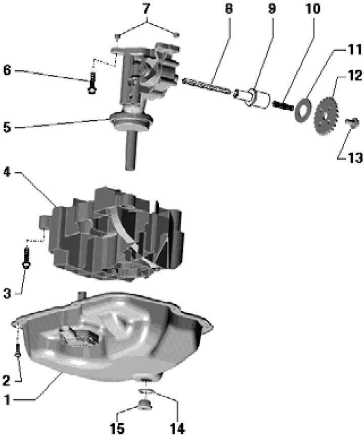
13.1a. Oil pump and lower oil sump installation details:
1 - Lower section of the oil pan with oil level and temperature sensor;
2 - Bolt, to be replaced, 5 Nm, then 8 Nm, then tighten by 90°;
3 - Bolt, to be replaced, 8 Nm, then tighten to an angle of 90°;
4 - Relief plate;
5 - Oil pump with cold engine pressure relief valve (11 bar) and pressure regulating valve (at 3.5 bar), don't take it apart;
6 - Bolt, 23 Nm;
7 - Centering bushings;
8 - Oil pump drive shaft;
9 - Clutch;
10 - Spring;
12 - Pump sprocket 5, the side with letters faces the engine;
13 - Bolt, 64 Nm;
14 - Gasket, subject to replacement;
15 - Drain plug: M14 - 30 Nm, M24 - 50 Nm.
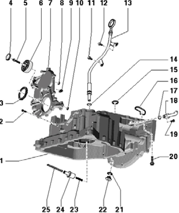
13.1b. Upper Oil Pan Section Installation Details:
1 - Upper section of the oil pan;
2, 11, 12, 19 - Bolt, 9 Nm;
3 - Front crankshaft oil seal;
4 - Roller plug 6;
5 - Bolt, 23 Nm;
6 - Intermediate roller of the drive belt;
7 - Front sealing flange;
8, 10, 14 - O-ring, subject to replacement;
9 - Sealing elements, 2 pcs.;
13 - Oil dipstick guide tube;
15, 16, 21 - Gasket, subject to replacement;
18 - Turbocharger oil return line;
20 - Bolt, 5 Nm, then 15 Nm;
22 - Service hole plug, 35 Nm;
23 - Spring;
24 - Clutch;
25 - Oil pump drive shaft.
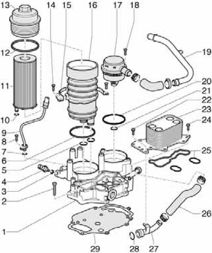
13.1c. Oil cooler, PCV valve, and oil filter housing installation details (bUG/BUN engines):
1 - Mounting plate for oil cooler, PCV valve and oil filter housing;
2, 8, 14, 18, 22, 24 - Bolt, 9 Nm;
3, 6, 12, 25, 29 - Gasket, subject to replacement;
4 - Engine oil pressure switch, with grey insulation, 20 Nm;
5, 7, 10, 20, 21, 28 - Sealing rings, subject to replacement;
9 - Turbocharger oil supply line;
11 - Filter element;
13 - Cover, 35 Nm;
15 - Holder;
16 - Oil filter housing with bypass valve (for the difference in pressure between the ascending and descending flows of 2-3 bar);
17 - PCV pressure control valve;
19 - PCV tube;
23 - Oil cooler with bypass valve (for the difference in pressure between the ascending and descending flows of 2-3 bar);
26 - Coolant hose;
27 - Front coolant pipe.
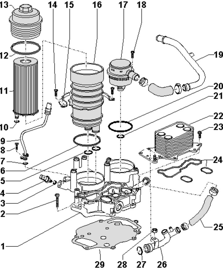
13.1d. Installation details of the oil cooler, pressure regulating valve and oil filter housing (cASA/CASB engines, SATA, SSMA):
1...21 - See captions to illustration 13.1c;
22 - Oil cooler with bypass valve (for the difference in pressure between the ascending and descending flows of 2-3 bar);
23 - Bolt, 9 Nm;
24, 29 - Gasket, subject to replacement;
25 - Coolant hose;
26 - Front coolant pipe;
27 - O-ring, must be replaced;
28 - Nut, 9 Nm.
2. Engine oil level and temperature sensor (4 in the illustration) is secured to the lower section of the oil pan with three nuts (1), tightened to 9 Nm.
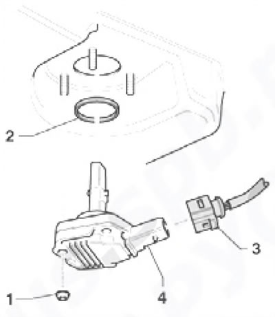
13.2. Details of installation of engine oil level and temperature sensor.
After removing the sensor, its gasket (2) should be replaced.
Removing and installing the lower section of the oil pan
3. Remove the drive belt and its tensioner (see Section 6).
4. Remove the left coolant pipe (see Chapter 3) and air purifier (see Chapter 4).
5. On both sides of the engine, loosen the nuts securing the engine brackets to the supports (see illustration 5.6).
6. Remove the front left wheel arch liner (see Chapter 10).
7. Follow the steps described in paragraphs 8-13 Section 5.
8. Place a transmission jack under the subframe (see illustration).
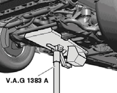
13.8. Transmission jack under the subframe.
Remove the bolts (4 in illustration 4.51) and carefully lower the subframe on the jack. Then unscrew the bolts (3) securing the engine crossmember and place it on the subframe.
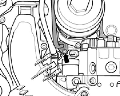
9. Disconnect the engine oil level/temperature sensor connector (1 in the illustration).
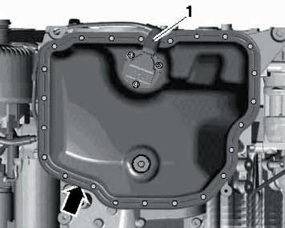
13.10. Connector (1) of engine oil level/temperature sensor and oil pan (arrow).
Drain the engine oil (see Chapter 1), unscrew the bolts and remove the lower section of the engine oil pan (arrow).
Note: There is still some oil left in the pan.
10. Using a drill with a plastic brush attachment, remove any remaining sealing materials from the mating surfaces of the upper and lower sections of the oil pan. Clean mating surfaces from oil and grease.
11. Apply a 2mm bead of silicone sealant to the tray as shown in the illustration.
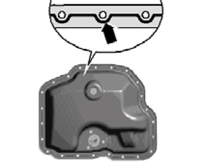
13.11. Sealant application diagram.
After applying the sealant, the tray should be installed within 5 minutes.
12. Install the pan, tighten all its bolts in a diagonal order to 5 Nm, then tighten them in the same order to 10 Nm and finally tighten them to an angle of 90°.
13. Install the subframe (see chapter 9), crossmember and engine mounts (see section 5). Install the remaining parts.
14. Finally, add engine oil (see Chapter 1).
Removal and installation the oil pump
Note: To loosen/tighten the bolt (13 in illustration 13.1a) when securing the pump sprocket, hold the sprocket from turning with a #3212 wrench. If the bolt cannot be tightened to the specified torque, remove the lower section of the oil pan with the damper plate and hold the oil pump drive shaft with an open-end wrench.
15. Remove the lower section of the oil pan (see subsection above).
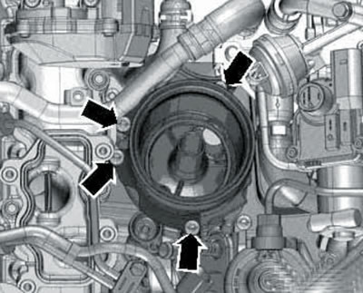
16. Remove the bolts (see illustration) and remove the sedative plate.
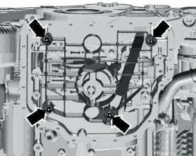
13.16. Fastening the damper plate.
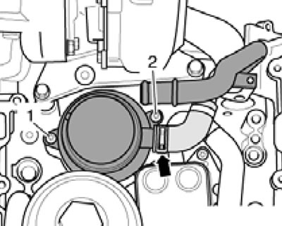
17. Remove the bolts (1 and 2 in the illustration).
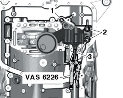
13.17. Removing the oil pump.
Hold the drive shaft (3) of the pump with long pliers VAS6226 and press it against the spring resistance. Remove the oil pump (its drive shaft remains in place).
18. Installation is carried out in reverse order. Use new sealing elements. Before installation, make sure that the pump has two centering bushings.
Removal and installation the upper section of the oil pan
19. Remove the timing chain covers (see Section 8) and the auxiliary drive chain (see section 10).
20. Remove the front sealing flange (see Section 7) and oil pump (see subsection above).
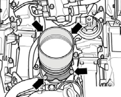
21. Remove the bolts (1-4 in the illustration) and press the upper section of the oil pan out of the spring pins of the cylinder block.
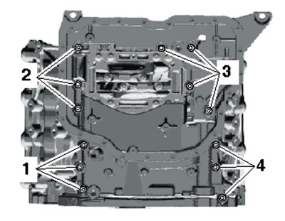
13.21. Bolts (1-4) for fastening the upper section of the oil pan.
22. Using a drill with a plastic brush attachment, remove any remaining sealing materials from the mating surfaces of the cylinder block and the upper section of the oil pan. Clean mating surfaces from oil and grease.
23. Install the gaskets (1 and 2 in the illustration). Apply a bead of silicone sealant (arrows) to the groove on the upper mating surface of the upper oil pan section. The bead should completely fill the groove and extend 1.5-2.0 mm beyond it. After applying the sealant, install the upper oil pan section within 5 minutes.
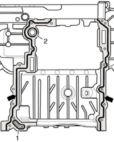
13.23. Sealant application diagram.
24. Install the top section of the tray and tighten its bolts (1-4 in illustration 13.21) with a force of 5 Nm, and then in the same order tighten them to a force of 15 Nm.
25. Install the remaining parts in the reverse order of their removal. On CASA/CASB engines, to ensure the coolant pipe is tight, it should be removed and the sealing ring replaced. Finally, fill the engine oil (see Chapter 1).
Removal and installation the oil cooler
26. Drain the coolant (see chapter 3).
27. Remove the upper and both lower sections of the intake manifold (see Chapter 4).
28. On CASA/CASB engines, remove the oil filter housing (see the relevant subsection below), as well as the "V338" activator for EGR circulation control (see chapter 4).
29. On BUG/BUN engines, remove the fuel injection pump drive belt and the fuel injection pump itself (see Chapter 4).
30. Remove the EGR cooler (see chapter 4).
31. On CASA/CASB engines, loosen the nut (1 in the illustration) and slightly turn the upper coolant pipe in the direction of the arrow.
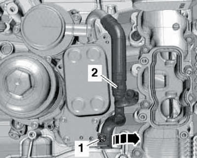
13.31. Separating the upper coolant pipe (cASA/CASB engines).
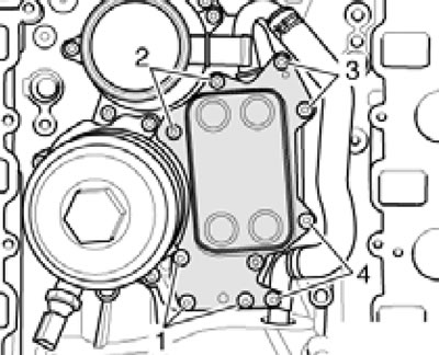
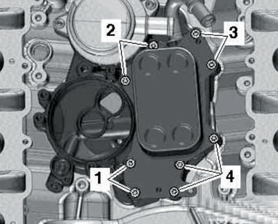
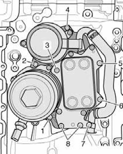
32. Remove the bolts (1-4 in the illustrations) and remove the oil cooler.
13.32a. Oil cooler mounting (bUG/BUN engines).
13.32b. Oil cooler mounting (cASA/CASB engines).
33. Installation is carried out in reverse order. Use new sealing elements. Finally, fill up with engine oil and coolant (see chapter 1).
Removal and installation the oil filter housing (bUG/BUN engines)
34. Remove the top engine cover (see Section 19 of Chapter 1).
35. Remove the union nuts (1-4 in the illustration) and disconnect the high-pressure fuel lines.
13.35. Nuts for fastening pressure fuel pipes.
36. Remove the upper section of the intake manifold (see Chapter 4).
37. Unscrew the filter element cover with a 32 mm head and remove it together with the filter element. Remove the filter element from the cover (see Section 6 of Chapter 1).
38. Disconnect the oil supply line from the mounting plate (see illustration).
13.38. Oil supply line bolt on mounting plate.
39. Unscrew the bolts securing the oil filter housing holders (see illustration).
13.39. Fastening the oil filter housing holders.
40. Make loops from two plastic zip ties (2 and 3 in the illustration) and secure them to the groove of the filter housing using the third clamp (1).
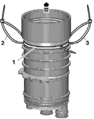
13.40. Removing the oil filter housing.
Pull the hinges and remove the oil filter housing.
41. Installation is carried out in reverse order. Use new seals, a new filter element and fresh oil.
Removal and installation the oil filter housing (cASA/CASB engines)
42. Remove the top engine cover (see Section 19 of Chapter 1).
43. Remove the electrical wiring connector (2 in the illustration) from the bracket and move it to the side.
13.43. Electrical wiring connector (2).
44. Disconnect the oil supply line from the mounting plate (see illustration 13.38).
46. Remove the filter element (see Section 6 of Chapter 1).
47. Unscrew the bolts securing the oil filter housing holders (see illustration).
13.47. Fastening the oil filter housing holders.
48. Follow the steps described in paragraphs 40-41.
Removal and installation the PCV pressure control valve
49. Drain the coolant and remove the coolant pipe: on BUG/BUN engines - the rear one, and on CASA/CASB engines - the rear right one (see Chapter 3).
50. Remove the upper and lower sections of the intake manifold (see Chapter 4). On BUG/BUN engines - both lower sections, and on CASA/CASB engines - only the right one.
51. Remove the EGR cooler (see Chapter 4).
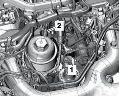
52. Disconnect the PCV hose from the PCV valve (arrow in the illustration), remove two bolts (1 and 2) and remove the PCV valve.
13.52. Connection (arrow) and fasteners (1 and 2) of the PCV valve.
53. Installation is carried out in reverse order. Use new sealing elements. Finally, fill up the coolant (see Chapter 3).
Removal and installation the mounting plate on BUG/BUN engines
54. Drain the coolant (see Chapter 3).
55. Remove the upper and both lower sections of the intake manifold (see Chapter 4).
56. Remove the rear coolant pipe (see Chapter 3).
57. Remove the fuel injection pump drive toothed belt and the fuel injection pump itself (see Chapter 4).
58. Remove the EGR cooler (see chapter 4).
59. Remove the bolts (1-8 in the illustration) and remove the mounting plate together with the oil cooler, PCV valve and oil filter housing installed on it.
13.59. Mounting plate fastener (BUG/BUN).
60. Installation is carried out in reverse order. Use new sealing elements. Tighten the mounting plate bolts in a diagonal pattern, starting from the inside and working outward. Finally, fill the engine oil (see Chapter 1) and coolant (see Chapter 3).
Removal and installation the mounting plate on CASA/CASB engines
61. Drain the coolant (see Chapter 3).
62. Remove the upper and right lower sections of the intake manifold (see Chapter 4).
63. Remove the EGR cooler (see Chapter 4).
64. Disconnect the coolant hose (2 in illustration 13.31) from the upper coolant pipe, loosen the nut (1) and slightly turn the pipe in the direction of the arrow.
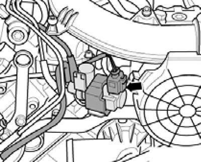
65. Disconnect the low pressure engine oil pressure sensor connector "F1" (see illustration).
13.65. Connector D/V "F1" low oil pressure.
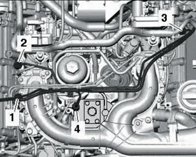
66. Remove the bolts (1-6 in the illustration) and remove the mounting plate together with the oil cooler, PCV valve and oil filter housing installed on it.
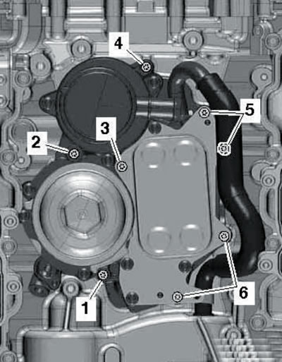
13.66. Mounting plate fastener (CASA/CASB).
67. Installation is carried out in reverse order. Use new sealing elements. Tighten the mounting plate bolts in a diagonal pattern, starting from the inside and working outward. Finally, fill the engine oil (see Chapter 1) and coolant (see Chapter 3).
Removal and installation of the "F1" low-pressure engine oil control valve (bUG/BUN engines)
68. Remove the top engine cover (see Section 19 of Chapter 1).
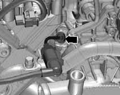
69. Separate the EGR valve from the holder (arrow in the illustration).
13.69. EGR valve connector.
70. Disconnect the connector (see illustration) and turn out D/V "F1".
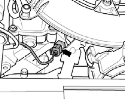
13.70. Electrical wiring connector D/V "F1".
71. Installation is carried out in reverse order. Use new D/V gasket "F1".
Removal and installation of the "F1" low-pressure engine oil control valve (cASA/CASB engines)
72. Remove the EGR cooler pump "V400" (see Chapter 4).
73. Disconnect the connector D/V "F1" of the low pressure engine oil (see illustration 13.65) and unscrew this D/V using a 24 mm extended head with a hinge.
74. Installation is carried out in reverse order. Use new D/V gasket "F1".
[This article was copied from an online resource AudiManual.ru]