
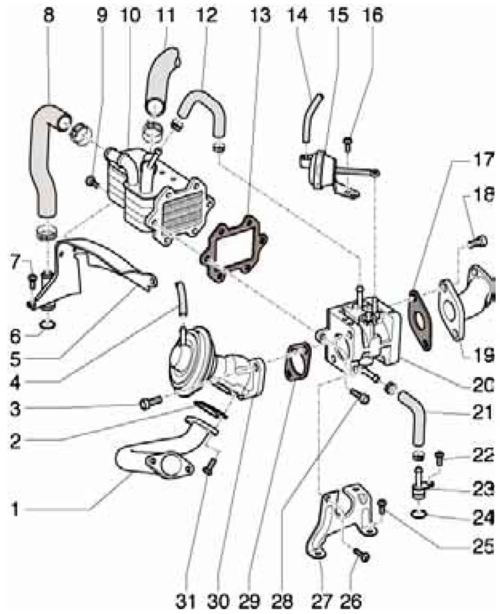
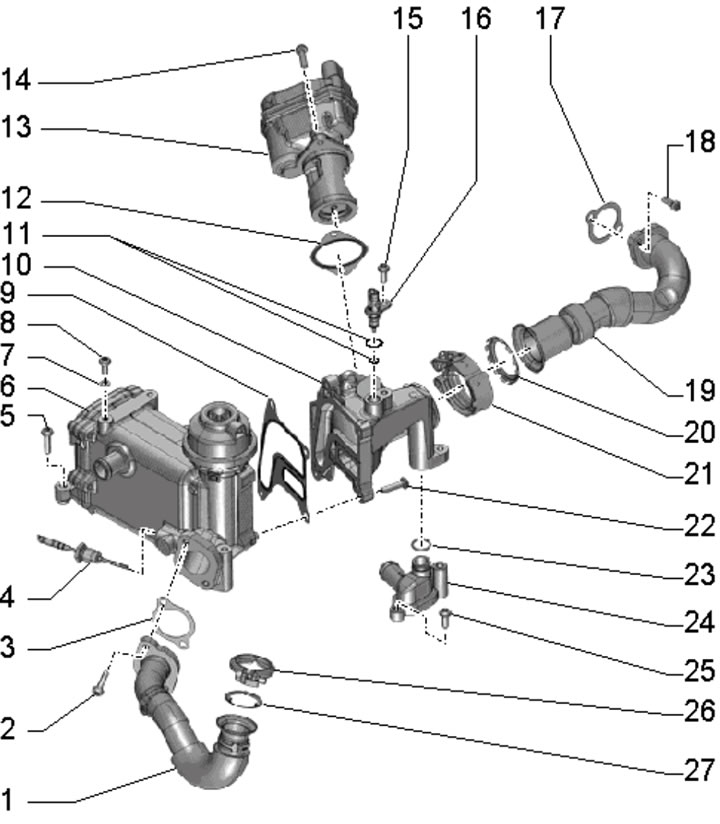
18.1a. Installation details of EGR system components for 3.0L models with BUG/BUN engines:
1, 19 - EGR connecting pipe;
2, 13, 17, 29 - Gasket, subject to replacement;
3, 18 - Bolt, 25 Nm;
4 - Vacuum hose;
5 - EGR radiator bracket, with connection for coolant hose;
6 - O-ring, must be replaced;
7, 9, 22, 25, 26, 28, 31 - Bolt. 9 Nm;
8, 11, 12, 21 - Coolant hose;
10 - EGR radiator;
14 - Vacuum hose from the EGR cooler switching valve "N345";
15 - Vacuum block for EGR switching function;
16 - Bolt, 4 Nm;
20 - EGR radiator switching valve;
23 - Coolant hose connection;
27 - Damper bracket 20;
30 - Mechanical EGR valve.
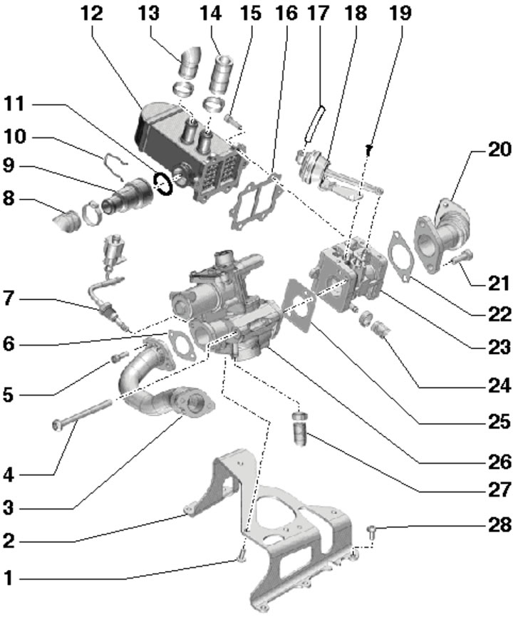
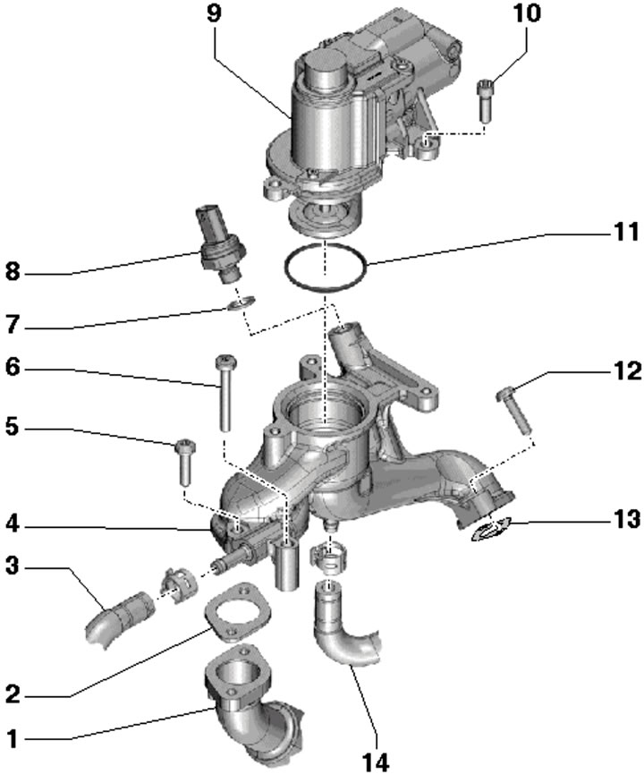
18.1b. Installation details of EGR system components for 3.0L models with CASA/CASB engines:
1, 5, 15, 28 - Bolt, 9 Nm;
2 - EGR bracket;
3, 20 - EGR connecting pipe;
4, 21 - Bolt, 25 Nm;
6, 16, 22, 25 - Gasket, subject to replacement;
7 - EGR temperature sensor "G98";
8, 13, 14, 24, 27 - Coolant hose;
9 - Connection to thermostat for EGR;
10 - Retainer;
11 - O-ring, must be replaced;
12 - EGR radiator;
16 - Vacuum hose from the EGR cooler switching valve "N345";
17 - Vacuum block for EGR switching function;
19 - Bolt, 4 Nm;
23 - EGR radiator switching valve;
26 - Activator "V338" EGR, with position sensor "G212".
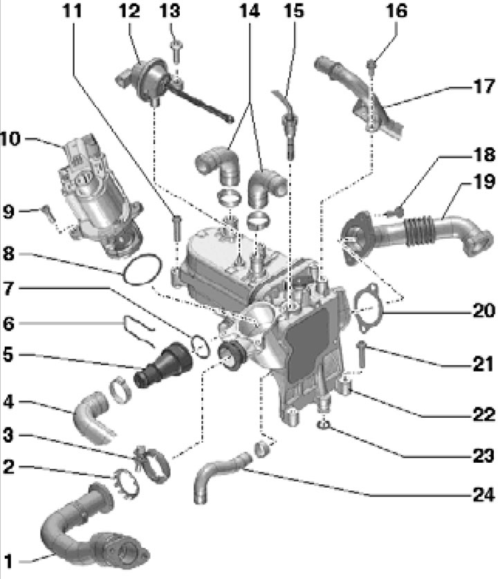
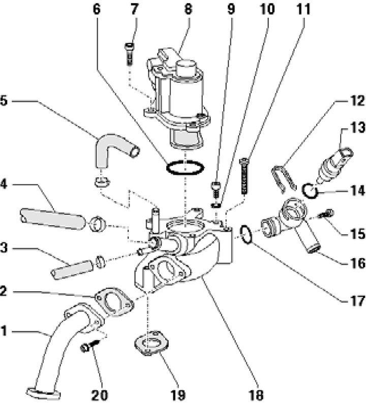
18.1c. Installation Details of the EGR System Components for 3.0L SCR Models (SATA, SSMA) - part 1 of 2:
1 - EGR pipe;
2 - Sealing element, subject to replacement;
3 - Clamp, 9 Nm;
4 - Coolant hose;
5 - EGR thermostat, with connection;
6 - Retainer;
7, 8, 23 - O-ring, subject to replacement;
9, 11, 13, 16, 21 - Bolt, 9 Nm;
10 - Activator "V338" EGR, with position sensor "G212";
12 - Vacuum block for EGR switching function;
14, 24 - Coolant hoses;
15* - EGR temperature sensor "G98", 45 Nm;
17 - PCV tube;
18 - Bolt;
19 - EGR pipe;
20 - Gasket, subject to replacement;
22 - EGR radiator with switching valve.
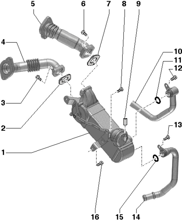
18.1d. Installation details of EGR system components for 3.0L SCR models (SATA, SSMA) - part 2 of 2:
1 - Additional EGR cooler;
2.7 - Gasket, subject to replacement;
3, 6, 8, 16 - Bolt, 9 Nm;
4 - EGR pipe;
5 - EGR pipe with catalytic converter;
9 - Vacuum hose with valve No. 2 "N381" for switching the EGR radiator;
10 - Rear coolant pipe;
11, 15 - Sealing ring, subject to replacement;
12, 13 - Bolt;
14 - Coolant pipe.
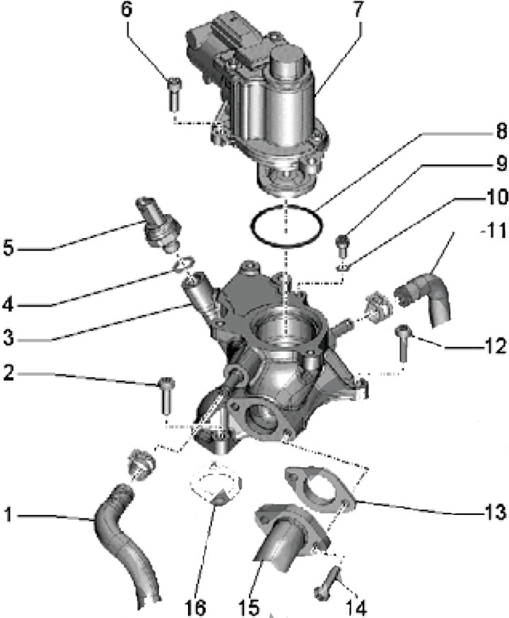
18.1e. Installation details of EGR system components for 2nd generation 3.0L models:
1 - EGR pipe to intake manifold;
2 - Bolts, first tighten by hand, then tighten the clamp 26, then tighten the bolts with a force of 9 Nm;
3, 7, 9, 12, 20, 27 - Gasket, subject to replacement;
4 - EGR temperature sensor "G98", 45 Nm;
5, 14, 15, 22, 25 - Bolt, 9 Nm;
6 - EGR radiator with switching valve;
8 - Bleed screw, 8 Nm;
10 - Connection;
11, 23 - Sealing rings, subject to replacement;
13 - Activator "V338" EGR, with position sensor "G212";
16 - Temperature sensor "G694" for regulating engine temperature;
17 - Gasket;
18 - Bolts, subject to replacement; first tighten by hand, then tighten clamp 21, then tighten the bolts with a force of 5 Nm and tighten them to an angle of 90°;
19 - EGR pipe from turbocharger;
21 - Screw clamp, subject to replacement; with part number "059131548C" - 5 Nm, and with part number "-D" - 3.5 Nm;
24 - Connection of coolant hose and pipe;
26 - Screw clamp, subject to replacement, 2.5 Nm.
18.1f. 4.2L EGR system component installation details on the left bank of cylinders:
1 - EGR pipe;
2, 13 - Gasket, subject to replacement;
3, 14 - Coolant hose;
4 - Right EGR connection;
5, 6, 12 - Bolt, to be replaced, 8 Nm, then tighten to an angle of 90°;
7 - Gasket (only on CCFA/CCFC engines), subject to replacement;
8 - Sensor No. 2 "G692" EGR pressure (only on CCFA/CCFC engines), 25 Nm;
9 - Activator "V339" EGR;
10 - Bolt, 9 Nm;
11 - Sealing ring. Subject to replacement.
18.1g. 4.2L Right Bank EGR Component Installation Details (bTR engine):
1 - Connecting tube;
2, 10, 19 - Gasket, subject to replacement;
3-5 - Coolant hose;
6, 14, 17 - Sealing ring, subject to replacement;
7, 15, 20 - Bolt, 9 Nm;
8 - EGR activator "V338";
9 - Bleed screw, 9 Nm;
11 - Bolt, to be replaced, 8 Nm, then tighten to an angle of 90°;
12 - Retainer;
13 - ECT sensor "G62";
16 - Connection of coolant hose and pipe;
18 - Right EGR connection.
18.1h. 4.2L Right Bank EGR Component Installation Details (cCFA/CCFC engines):
1 - Coolant pipe;
2, 14 - Bolt, subject to replacement, 8 Nm, then tighten to an angle of 90°;
3 - Left EGR connection;
4, 13, 16 - Gasket, subject to replacement;
5 - EGR pressure sensor "G691", 25 Nm;
6, 12 - Bolt, 9 Nm;
7 - EGR activator "V338";
8 - O-ring, must be replaced;
9 - Bleed screw (only on CCFC engine), 9 Nm;
10 - Gasket (only on CCFC engine), subject to replacement;
11 - Coolant hose;
15 - EGR pipe.
(This article was previously published on the resource: «AudiManual.ru»)