
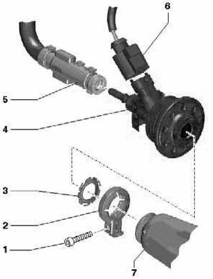
19.1a. Installation details of the AdBlue fluid supply injector for SATA, CCMA, and CLZB engines:
1 - Bolt, 5 Nm;
2 - Clamp;
3 - Gasket, subject to replacement;
4 - Nozzle "N474" for injection of liquid "AdBlue";
5 - "AdBlue" fluid hose;
6 - Electrical wiring connector;
7 - SCR catalytic converter.
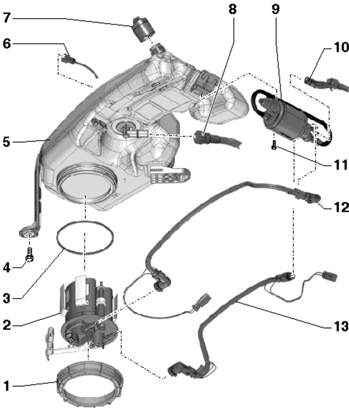
19.1b. Installation details of the active tank nozzle for the "AdBlue" liquid for SATA and CCMA engines:
1 - Union nut, subject to replacement;
2 - Reservoir with AdBlue liquid volume sensor "G684", AdBlue liquid temperature sensor "G685", heating element "Z102" and filter;
3 - Gasket, replaceable, dry installed;
4 - Bolt, 9 Nm;
5 - Active tank for "AdBlue" liquid, behind the rear right wheel arch liner;
6 - Transmission line, from pump "V436" to tank 5;
7 - Filler cap;
8 - Filling line, from tank 5 to passive tank;
9 - Pump "V437" for "AdBlue" liquid, with heating element "Z103" and pressure sensor "G686" for dosing "AdBlue" liquid;
10-Liquid metering line "AdBlue", from pump 9 to nozzle "N474";
11 - Bolt, 1.8 Nm;
12 - Return line;
13 - Feed line.

19.1c. Installation details for the active AdBlue tank nozzle for SATA and CCMA engines:
1 - Lock washer, 1.5 Nm;
2 - Support plate;
3 - Bolt, 60 Nm;
4 - Passive tank for "AdBlue" liquid, on the rear left side of the body;
5, 14 - Bolt, 35 Nm;
6 - Filling line from the active tank;
7 - Ventilation line to the active tank;
8-AdBlue liquid metering line, from pump "V437" to nozzle "N474", with heating element "Z104";
9 - Transmission line to the active tank;
10 - Bolt, 1.8 Nm;
11 - Transfer pump "V436" of "AdBlue" liquid;
12 - Hose from tank 4 to pump 11;
13 - Clamp.