
The multi-point injection system creates the ideal conditions for highly efficient mixture preparation. Each cylinder has its own valve injector, which injects the fuel directly in front of the intake valve. The injectors are controlled electronically, have an electromagnetic drive and operate in intermittent mode.
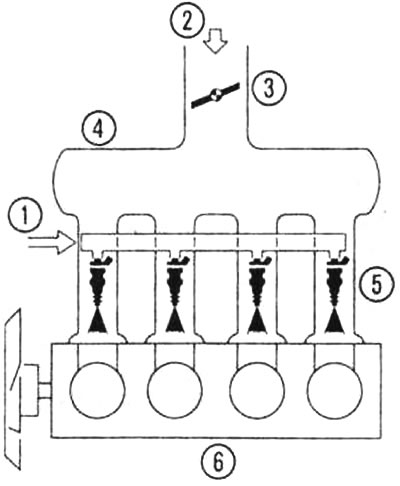
The principle of multi-point injection in a 4-cylinder engine: 1 - fuel, 2 - air, 3 - throttle valve, 4 - intake manifold, 5 - injectors, 6 - engine.
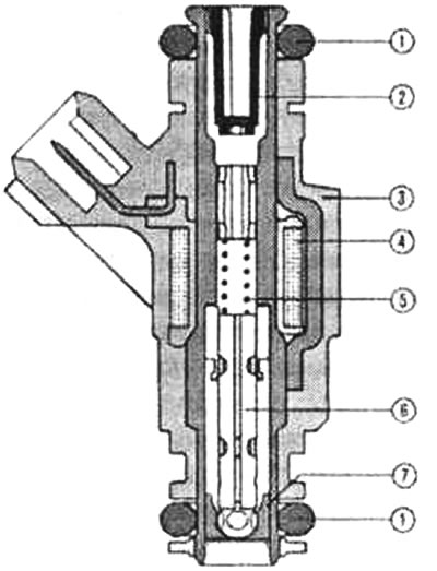
Valve injector in section (principle): 1 - O-rings, 2 - filter mesh, 3 - valve body with electrical connection element, 4 - coil, 5 - spring, 6 - valve needle with electromagnet anchor, 7 - valve seat with washer for injection hole. The figure shows a Bosch injector designed for Motronic control systems.
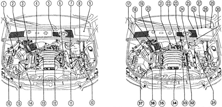
Motronic system components for ASN engines (3.0L, 6 cylinders): 1 - Solenoid valve N80 for the activated carbon canister, 2 - Air mass meter G70 with intake air temperature sensor G42, 3 - Hall sensor G300 for the exhaust camshaft (1st row of cylinders), 4 - Hall sensor G40 for intake camshaft (1st row of cylinders), 5 - pressure sensor G294 for brake booster, 6 - Hall sensor G163 for intake camshaft (2nd row of cylinders), 7 - Hall sensor G301 exhaust camshaft (2nd row of cylinders), 8 - ignition coils with powerful final stage (2nd row of cylinders: cylinders 4, 5 and 6), 9 - electronics unit in the battery section (including engine control unit J220), 10 - Pump V192 for brake booster, 11 - Valves N₂08 and N319 for adjusting intake and exhaust camshaft (2nd row of cylinders), 12 - valve injectors (2nd row of cylinders: cylinders 4, 5 and 6), 13 - valve injectors (1st row of cylinders: cylinders 1, 2 and 3), 14 - valves N₂05 and N318 for regulating the intake and exhaust camshaft (1st row of cylinders), 15 - ignition coils with powerful final stage (1st row of cylinders: cylinders 1, 2 and 3), 16 - V101 engine for additional air pump, 17 - oxygen sensor G39 with heating device Z19 before catalytic converter (1st row of cylinders), 18 - Holder for plug connections, 19 - Oxygen sensor G130c with heating device Z29 after catalytic converter (1st row of cylinders), 20 - Coolant Temperature Sensor G62, 21 - Throttle Valve Control Unit 338, 22 - Secondary Air Boost Valve N112, 23 - Engine Speed Sensor G28, 24 - Holder for Plug Connections, 25 - Accelerator Pedal Position Sensors G79 and G185, 26 - Fuel Pump Relay L 7, 27 - Brake Light Switch F and Brake Pedal Position Sensor F47, 28 - Clutch Pedal Position Sensor F36, 29 - Combined Instrument Cluster with Warning Lamps, 30 - Lambda Sensor G131 with Heater Z30 After Catalytic Converter (2nd row of cylinders), 31 - Oxygen sensor G108c heating device Z28 before catalytic converter (2nd row of cylinders), 32 - fuel pressure regulator, 33 - knock sensor 2/G66 (2nd row of cylinders), 34 - valve N156 for switching the intake gas line with variable tract length, 35 - knock sensor 1/G61 (1st row of cylinders), 36 - circulation pump of liquid cooling system V51, 37 - connection to ground (on the right engine mount).
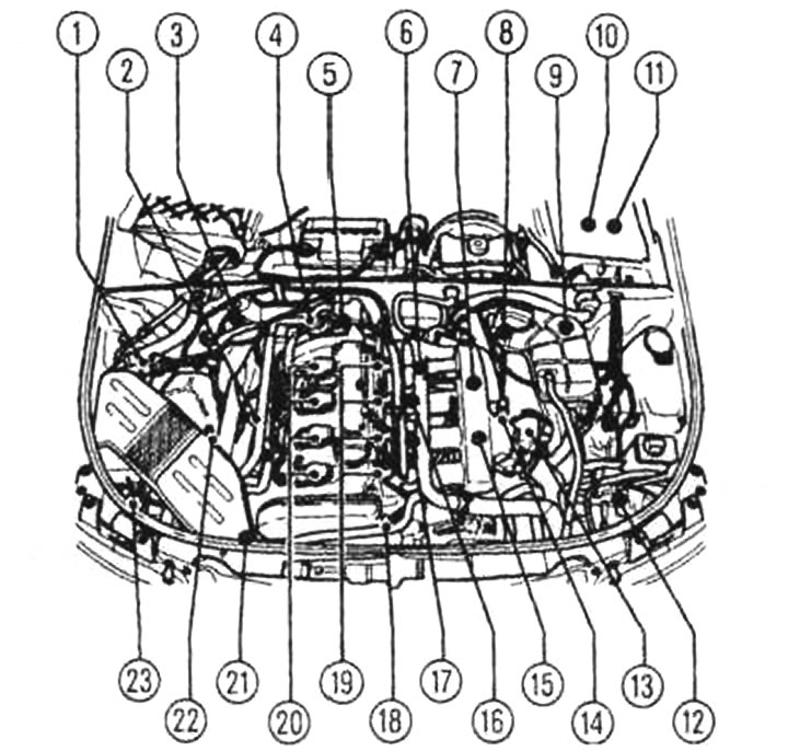
Motronic system components for ALT engines (2.0 l): 1 - oxygen sensor G130 (55 Nm) after the catalytic converter, 2 - additional air boost valve N112, 3 - coolant temperature sensor G62 (9 Nm), 4 - valve 1 for adjusting the camshaft N₂05, 5 - engine speed sensor G28. 6 - Fuel pressure regulator, 7 - Throttle valve control unit J338, 8 - Three-pin connector for knock sensor G61, 9 - Four-pin connector for lambda probe G130, 10 - Three-pin connector for engine speed sensor G28, 11 - Three-pin connector for knock sensor G66, 12 - Six-pin connector for lambda probe G39, 13 - Engine control unit J361, 14 - Relay J299 for additional air pump and supply relay for engine control unit, 15 - Brake servo vacuum pump, 16 - Vacuum box for intake manifold changeover, 17 - Solenoid valve N156 for variable intake manifold changeover, 18 - Intake air temperature sensor G42, 19 - Camshaft position sensor (hall sensor) G40, injectors (N30...N33), 20 - ignition coils, 21 - lambda probe G39 (55 Nm), 22 - air mass meter G70, 23 - solenoid valve N80 for activated charcoal canister. The following components are not shown in the illustration: brake light switch F and brake pedal position sensor F47 on the pedal bracket, diagnostic socket on the driver's side, fuel pump relay on the relay holder behind the storage compartment on the driver's side, clutch pedal position sensor F36 on the pedal bracket near the clutch pedal, accelerator pedal position sensors G79 and IV 185 in the housing on the accelerator pedal, and the electronic accelerator pedal indicator in the combined instrument panel.
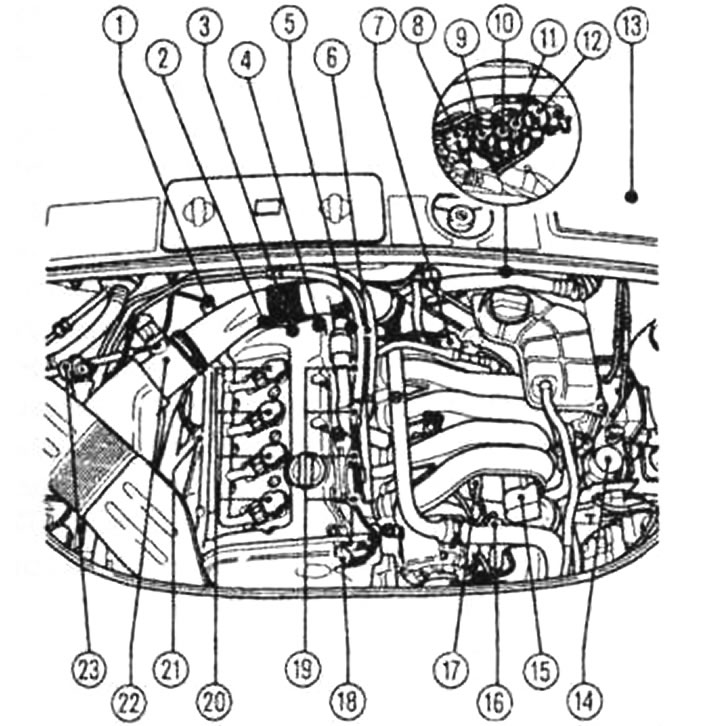
Motronic System Components for AVJ Engines (1.8L turbocharged): 1 - Solenoid valve N80 for the activated charcoal canister, 2 - Lambda probe G39 (55 Nm), 3 - Lambda probe G130 (55 Nm), 4 - Combination valve for secondary air charging, 5 - Coolant temperature sensor G62, 6 - Engine speed sensor G28, 7 - Secondary air charging valve N112, 8 and 9 - Holders for plug connections, 10 and 11 - Electronic unit in the battery compartment (including engine control unit J220 and two current relays: J271 for Motronic, J299 for the secondary air pump, 12 - Boost pressure sensor G31, 13 - Throttle valve control unit J338, 14 - Intake air temperature sensor G42, 15 - Wastegate valve N₂49 for turbocharger, 16 - Knock sensor G61, 17 - Knock sensor G66, 18 - Hall sensor G40, 19 - Injectors N30-N33, 20 - Ignition coils, 21 - Solenoid valve N74 for boost pressure limitation, 22 - Air mass meter G70, 23 - Engine V101 for secondary air pump. The following components are not shown in the illustration: brake light switch F and brake pedal position sensor F47 on the pedal bracket, diagnostic connector on the driver's side, fuel pump relay on the relay holder behind the storage compartment on the driver's side, clutch pedal position sensor F36 on the pedal bracket near the clutch pedal, accelerator pedal position sensors G79 and G185 in the housing on the accelerator pedal, and the electronic accelerator pedal indicator in the combination meter.
External mixture formation
In the petrol variants of the Audi A4, which are still predominant today, external mixture formation is still used: the fuel is injected before the intake valves. In this case, the fuel-air mixture charged into the cylinder is usually distributed homogeneously throughout the entire combustion chamber.
Even with this indirect multi-point injection, the mixture does not have to travel a long distance in the gas line due to the fact that the intake and exhaust valves are located next to each other. The risk of gasoline settling on the wall of the intake manifold, especially when the engine is cold, is reduced.
Electronic fuel injection systems (Motronic by Bosch or Simos by Siemens) differ depending on the engine type, but their operating principle is the same. The systems differ from each other in terms of the design of individual components, parameters and installation location. This is clearly shown in the following figures, which show three versions of the Motronic system.
The illustrations of Motronic systems and their individual components clearly illustrate the incredible complexity of modern engines and engine management systems. Without special auxiliary means and expensive measuring and testing equipment, neither qualified maintenance nor meaningful repair of these systems is possible. Rather, we wanted to demonstrate how meaningful testing of injectors is carried out using appropriate measuring equipment.
The instructions for replacing the throttle control cable, which were always given in such publications, are no longer necessary, since the Audi A4 only has an electronic accelerator pedal. Therefore, we only inform you about the removal and installation of the accelerator pedal module.
It is important to have at least a general idea of the interaction of the individual components of the Motronic system and to know where they are installed. This will make it easier for you to understand the data of the fault diagnostics carried out in the workshop and will allow you to exchange opinions with specialists regarding repairs. Often, it is impossible to do without replacing individual components and entire units. For this reason, in our book we also provide a drawing with the components of the intake manifold switchover device as the most important component of the ignition and fuel injection system of the six-cylinder ASN engine.
(This publication is borrowed from the resource: AudiManual)