
Air flow meter. The air flow meter is located between the air filter and the throttle valve. It records not only how much air enters the engine, but also the air density. The air density determines the proportion of oxygen, which plays a decisive role in the combustion process. The amount of air filling is used to calculate the amount of fuel injected, the ignition timing, and the current torque delivered by the engine.
The Audi A4 uses a hot-film air flow meter. An electrically heated sensor plate is positioned in the intake air flow, which cools the plate. The control circuit regulates the heating current so that the temperature of the plate is a certain amount higher than the air temperature. The heating current is used by the control unit as a measure of the air mass flow.
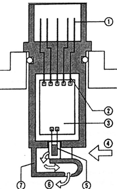
Air flow meter located on the air filter housing: 1 - electrical terminals, 2 - electrical connections, 3 - measurement results processing unit, 4 - inlet, 5 - sensor element in hot-film air flow meter, 6 - outlet, 7 - housing.
Intake manifold pressure sensor. This sensor is pneumatically connected to the intake manifold, it senses the absolute pressure in the intake manifold. The sensor can be built into the control device, it can also be located directly in the intake manifold or near it.
Throttle position sensor. This sensor determines the angular position of the throttle valve, i.e. it provides information on how the driver accelerates. If the air flow meter fails, the control device uses the signals from this sensor to determine the engine load.
Rotation speed sensor. This sensor not only provides information about the engine speed, as its name suggests, but the position of the sensor on the crankshaft serves as a reference point that allows the control device to determine the position of the crankshaft, and with it the position of each cylinder.
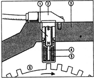
Inductive speed sensor. This sensor is located above the ferromagnetic ring gear on the crankshaft. Rotation affects the magnetic flux in the sensor's permanent magnet 1 with a north (N) and south (S) pole. 2 - housing, 3 - engine crankcase, 4 - soft iron core, 5 - winding (interacts with the sensor magnet), 6 - toothed wheel with a gap between the teeth: the absence of two teeth on the sensor wheel is put in correspondence with a certain position of the crankshaft for cylinder No.1.
The position of the camshaft is also important, the data on which is obtained using a phase sensor, which is also called hall sensor. Thanks to this sensor, the control unit receives information about which cylinder is currently in the compression stroke, on the basis of which the individual ignition coils receive an ignition signal from the control unit.
Ambient air pressure sensor (altimeter). This sensor is located directly above the control unit. It allows you to accurately determine the density of the surrounding air, this information is used in numerous diagnostics.
In a turbocharged engine, it is also used boost pressure sensor.
Oxygen sensor. The oxygen sensor is always located in the exhaust manifold. Modern powerful engines have several sensors (before and after the catalytic converter). Based on the exhaust gas composition, the oxygen sensor measures the air-to-fuel ratio, a numerical measure of the air-to-fuel ratio in a new portion of the working mixture. For complete combustion of one kilogram of gasoline, approximately 14.5 kilograms of air are required, which corresponds to an air-to-fuel ratio of 1. A ratio greater than 1 means a lean mixture with a large amount of air, while a ratio less than 1 means a rich mixture.
The catalytic converter works optimally only when the excess air coefficient is equal to 1. If this ratio is not provided, the electronic-digital engine control device, by changing the amount of fuel injected, changes the ratio between the amount of air and fuel in the mixture accordingly. The oxygen sensor operates only starting from 350°C, so there is no regulation immediately after a cold start. To reduce the duration of this phase, a heated oxygen sensor is used.
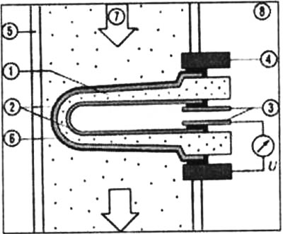
Oxygen sensor in the exhaust pipe: 1 - special ceramics, 2 - electrodes, 3 - contact, 4 - contact with the housing, 5 - exhaust pipe, 6 - (porous) ceramic protective layer, 7 - exhaust gas, 8 - outside air. U - voltage.
Fuel knock sensor. This sensor is built into the cylinder block and registers uneven (detonation) combustion and accordingly regulates the ignition timing.
Engine temperature sensor. Located in the coolant circulation circuit, it transmits data on the coolant temperature to the control device.
Intake air temperature sensor. Located in the intake channel.
(Read the original source on the website: AUDImanual)