
Table of contents: Continuous improvement ↓ Direct injection of gasoline ↓ Electronic control device ↓ Switching system on a single CAN bus ↓
it goes without saying that the fuel supply and metering, ignition and exhaust gas control in the Audi A4 are state-of-the-art. These tasks are performed by complex, computer-controlled systems that interact with a modern ignition system. All this has a positive effect on the efficiency, environmental friendliness and reliability of the engine.
However, for enthusiasts who like to do everything themselves, including experienced car enthusiasts, these achievements will most likely bring some disappointment. It is unlikely that you can put your hand to it here.
The electronically loaded engine control unit, which is located in the battery compartment, constantly calculates the amount of fuel injected and the injection moment for each combustion process based on a large amount of data. Quite understandable electromechanical equipment has evolved into a highly sophisticated computer-based engine control device. This device is programmed using multidimensional characteristics, uses data from a fault recorder and uses a self-diagnostic system to detect failures.
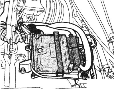
Placement: The engine control unit is located next to other electronic components in the electronics box, which is located on the left side of the battery compartment. The illustration shows the ASN six-cylinder engine control unit as an example.
Since the data for the petrol injection system are also of great importance when calculating the ignition timing, the control unit also takes over the regulation of the ignition timing. In the case of the Motronic engine control unit, (bosch company) or Simos (siemens company) it is no longer possible to separate the injection system and the ignition system from each other. Despite this, for clarity, we describe the components of the ignition system in a separate chapter.
Open large image in new window »
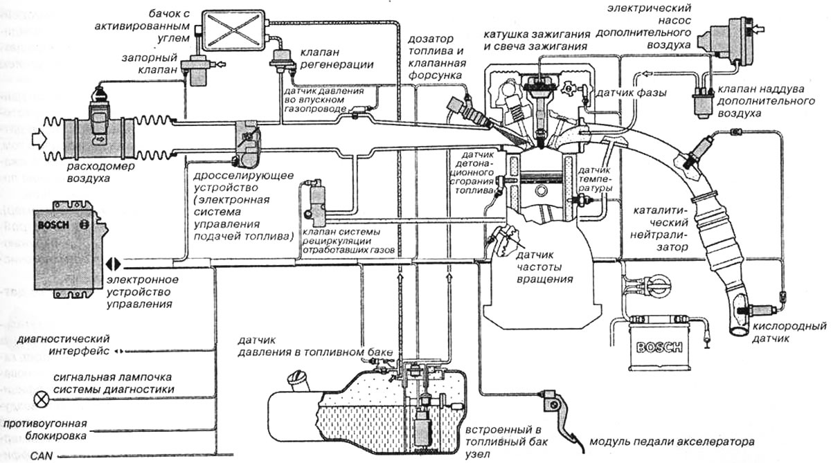
Functional system of the Motronic system. The control unit processes a large number of signals. In some cases, if the sensors fail, emergency programs are activated. However, if, for example, the speed sensor fails, the engine is turned off.
With the help of a complex electronic engine management system, low fuel consumption can be optimally achieved while maintaining strict exhaust gas composition limit values. To achieve this, the control unit must receive precise data on the current engine operating conditions. When a carburetor was used, the only variable that was regulated was the reduced pressure in the intake manifold. In the case of a central electronic engine management system, sensors located on and around the engine provide data on the temperature of the engine, coolant and intake air, air density, exhaust gas composition, engine load and shaft speed.
Since the computing device has all the necessary information, it is assigned additional tasks:
- speed control,
- regulation of exhaust gas composition,
- control of the evaporative fuel regeneration system,
- anti-knock control,
- exhaust gas recirculation system control,
- turbocharger control, since turbocharging is used,
- intake manifold switching control and camshaft adjustment.
Continuous improvement
In addition, the electronic digital engine control unit interacts with other vehicle systems. Together with the automatic transmission control unit, the electronic engine control system, which is constantly being improved and offers new features, ensures smooth gear shifting. This is achieved by slightly reducing the engine speed when shifting gears. The electronic digital engine control unit also communicates with the anti-lock and anti-skid system.
Direct injection of gasoline
The final step in the development of engine management systems is internal mixture formation, i.e. fuel injection directly into the combustion chamber. So far, systems are mainly used in which the mixture is formed outside the combustion chamber. However, since the end of summer 2001, when the 2.0 l FSI engine began to be installed, a new trend in the development of the Audi A4 has emerged. This engine is equipped with a direct gasoline injection system FSI.
The economic and ecological function of the engine management system, which consists in ensuring reduced fuel consumption and emissions as well as good engine performance, is most clearly demonstrated in the FSI engine. Electronic control using technically sophisticated injection pumps allows the correct amount of fuel to be injected for each engine mode and the corresponding start of injection to be set.
Electronic control device
The computing and switching device of the engine management system, based on the signals coming from the sensors, calculates control signals for the actuators, i.e. for the ignition coil, injectors, etc. The control device is located in a metal case, inside the case there is a printed circuit board with electronic components. This small, inconspicuous unit is located at the edge of the engine compartment, on the left side of the battery section.
The digital circuits of the control device are powered by a voltage regulator. The control device includes final stages that provide sufficient power for direct connection of the actuators. A protection circuit protects these final stages from short circuits to the housing and destruction due to electrical overload.
The Audi A4 engines are mainly controlled by electronic systems manufactured by Bosch. The ALT engine is equipped with a control unit ME 7, AVJ (turbocharged) — ME 7.5, and the six-cylinder ASN engine — the ME 7.1 control unit. In the two-valve four-cylinder engine (type ALZ), control is assigned to the Simos 3.4 electronic unit.
The above-mentioned diagnostic function allows you to identify faults that may occur in some final stages and, if necessary, disconnect the faulty output. Information about the fault is stored in a memory device. This information can be read in a specialized workshop using a special device. Faults are recorded as a printout of digital codes, these codes are processed in specialized workshops.
Switching system on a single CAN bus
Conventional switching systems in cars are characterized by the fact that each signal corresponds to a separate wire. The huge increase in data exchange between electronic components in modern engine management systems makes it difficult to use old switching systems. For some time now, it has become difficult to understand the intricacies of conventional cable harnesses.
The problem was solved by a switching system developed specifically for cars on a single CAN bus. Electronic control devices must have a serial CAN interface, this interface allows them to be connected to each other via the corresponding data bus.
In a car, CAN performs three important functions:
- interfacing of control devices with each other,
- ensuring the operation of body electronics and comfort (Multiplex),
- providing mobile communications.
The International Organization for Standardization provides for the use of CAN in automobiles as a standard. This standard is valid for data exchange at a speed of more than 125 kbps, in addition, there are two more protocols for data transfer speeds of less than 125 kbps.