
Repair Chevrolet Repair Toyota Repair Honda Repair AvtoVAZ Repair Mercedes-Benz Repair BMW Repair Opel
Home  |  Contacts  |  Sitemap  |    
English Русский
Български
Беларускі
Український
Српски
Hrvatski
Română
Polski
Slovenský
Magyar
AudiManual.ru


  • AUDI 80
  • AUDI 100
  • AUDI A3
  • AUDI A4
  • AUDI A6
  • AUDI A8
  • AUDI Q
  • OTHER
  • ARTICLES
B8 (2007-2015) B7 (2004-2008) B6 (2000-2006) B6 (2000-2006, petrol) B5 (1994-2001) B5 (1994-2001, petrol)

Direct injection of gasoline (Audi A4 B6)

  • Home
  • Audi A4
  • B6 (2000-2006, petrol)
  • Power unit
  • Injection and control system
  • Direct injection of gasoline
            0
In the summer of 2001, direct fuel injection was successfully implemented for the Audi A4 with a 2.0-liter petrol engine. Only by using direct fuel injection with stratified charge FSI can engine power be increased with lower or unchanged fuel consumption, and also to meet the exhaust emissions standards, which are becoming increasingly strict.

With FSI direct petrol injection technology, Audi has launched a new generation of engines that represent a huge leap forward in terms of efficiency. Compared to conventional engines with petrol injection into the intake manifold, the direct injection engine is more dynamic and powerful, delivers more torque and reduces fuel consumption by up to 15 percent.

This is made possible primarily by stratified charging in partial load mode. This means that the combustible mixture is only needed near the spark plug, while the rest of the combustion chamber is filled with a significant excess of air. This means that the engine does not need to be throttled. In addition, direct injection reduces heat loss. This means that the air layers around the mixture cloud isolate it from the cylinder and cylinder head.

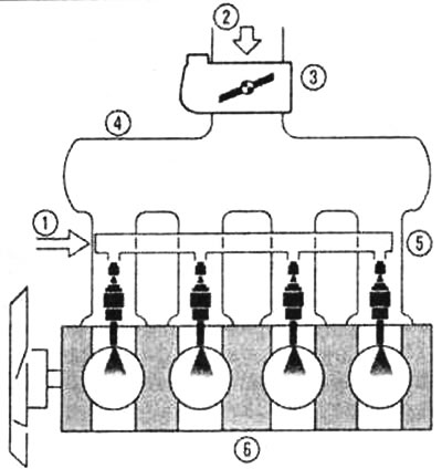
Unlike a manifold-injected engine, the fuel is injected directly into the combustion chamber. The injector, which is supplied with fuel via a single-plunger pump and a common fuel line, is located on the side of the cylinder head. The valve injector doses the fuel with millisecond precision and at a pressure of up to 110 bar.
The principle of direct gasoline injection: 1 - fuel, 2 - air, 3 - throttle valve (electronic…

The principle of direct gasoline injection: 1 - fuel, 2 - air, 3 - throttle valve (electronic accelerator pedal). 4 - intake manifold, 5 - valve injectors, 6 - engine.


Schematic representation of the Bosch-MED system (electronic control system for direct fuel…

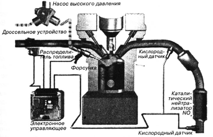
Schematic representation of the Bosch-MED system (electronic control system for direct fuel injection engines)


The fuel is injected in stratified charge mode during the compression stroke. It is then set in motion by the air that is admitted into the combustion chamber. The air, in turn, is set in targeted motion by a movable flap in the intake manifold, the intake channel and the special shape of the piston crown.

After this, the required effect of layered distribution of fuel in the charge is achieved: the fuel cloud, which together with air forms a combustible mixture and spreads within a limited space, is located around the spark plug at the moment of ignition. Due to the large angle of expansion of the jet, the fuel cloud almost does not touch the piston bottom, in addition, after combustion, an insulating layer of air is located between the ignited mixture and the cylinder wall. As a result, heat removal through the cylinder block is reduced, and this increases the efficiency of the engine.

The cylinder block and dimensions of the first representative of the new generation of engines are identical to the cylinder block and dimensions of the regular two-liter units A4 and A6. This engine is equipped with a fuel injection system through a common fuel line and a single-plunger injection pump. The cylinder head has not five, but four valves, which provides free space for the valve injector.


The variable-length intake manifold consists of two stages, so it provides two lengths of the tract: for high and low speeds. The permanently operating camshaft adjuster ensures the appropriate control of the valve opening time. On the exhaust side is one of the main components necessary for the effective reduction of exhaust gas toxicity - the exhaust gas recirculation system. This system works more efficiently than previous systems, it diverts up to 30 percent of the exhaust gas into the combustion chamber.

Tumble System


To implement a layered charge, it is necessary that the injection, the air flow inside the cylinder and the geometry of the combustion chamber are optimally coordinated with each other. To control the air flow in the intake tract, the Tumble system is used (tumble in English means "somersault, somersault"). By means of a special partition, the inlet channel is divided into upper and lower halves. The suction channels are located in the cylinder head, and special dampers are located on the side of the head, in a flanged multifunctional module. The pre-connected flap directs air either only through the upper part or through the entire cross-section.

In order to achieve an intensive cylindrical flow in the combustion chamber, a special flap is closed in stratified charging mode, and with it one of the two channels. In this mode, the fuel is injected only in the last third of the piston's upward movement, i.e. during compression. Thanks to the combination of a targeted air flow and a special piston geometry, which has a clearly defined combustion chamber cavity, the finely atomized fuel is optimally concentrated around the spark plug and reliably ignited.

The Tumble system firstly made it possible to combine the economical stratified charging mode with very high power and torque values for the first time. At high revs, the FSI engine operates like a conventional engine with intake manifold injection, but thanks to the higher compression, the engine efficiency increases.

(The original article is available on the online resource: AudiManual)
The article was checked by auto expert Alexey Ivanov
This article is available at russian, bulgarian, belarusian, ukrainian, serbian, croatian, romanian, polish, slovak, hungarian

Share information:
Previous articles
Audi A4 B6: Injection and control system
Next articles

Fuel injection system parts
Operating principle of the electronic engine management system
Fuel injection system — design description
Electronic accelerator pedal
What to do if the injection system malfunctions
Fuel injection system programming
Visual inspection of the injection system
Removal valve injectors


Similar articles on other Audi car models:
Fuel for gasoline engines Audi 80 B3 (1986-1991, petrol)
Removal injection nozzles Audi 100 C4 (1990-1994, petrol)
Direct injection device (diesel) Audi A3 Type 8L (1996-2003)
Electrical diagram of the control unit of the direct injection… Audi A6 C5 (1997-2004)
General information about the ignition and fuel injection system Audi A8 D2 (1994-2002)
Injection system Audi Q5 Type 8R (2008-2017)
General information about the fuel injection system Audi A2 (1999-2005)
Link to this page in different formats


Visitor comments

No comments yet


How much will 12 + 47 =


A4(B8, 2007-2015) 
  • General information
  • Operating instructions
  • Power unit
  • Petrol engines 1.8 l
  • Petrol engines 1.8/2.0 l
  • Petrol engines 3.0 l
  • Petrol engines 3.2 l
  • Fuel system (petrol)
  • Diesel engines 2.0 l (CA*)
  • Diesel engines 2.0 l (CJCB)
  • Diesel engines 2.7/3.0 l
  • Diesel engines 3.0 l
  • Fuel system (diesel)
  • Transmission
  • Manual gearbox 0B1
  • Manual gearbox 0B2
  • Manual gearbox 0B3
  • Manual gearbox 0B4
  • Automatic transmission 0B5
  • Automatic transmission 0B6
  • Automatic transmission 0AW
  • All-wheel drive system
  • Chassis
  • Front suspension
  • Rear suspension
  • Brake system
  • Steering system
  • Body
  • Exterior
  • Interior
  • Seats
  • Doors, locks and windows
  • Security system
  • Heating and air conditioning
  • Electrical equipment
  • Audio system
  • Power devices
  • Equipment and devices
  • Lighting and lamps
  • Electrical circuits
 
A4(B7, 2004-2008) 
  • General information
  • Introduction to manual
  • Troubleshooting
  • Operating instructions
  • Maintenance
  • Power unit
  • Petrol engines 2.0 (ALT)
  • Petrol engines 2.0 (TFSI)
  • Petrol engines 1.8 (MPI)
  • Diesel engines
  • Cooling system
  • Air conditioner
  • Fuel and exhaust system
  • Ignition system
  • Starting and charging
  • Transmission
  • Clutch
  • Manual gearbox
  • Automatic gearbox
  • Drive shafts
  • Chassis
  • Brake system
  • Front suspension
  • Rear suspension
  • Steering
  • Body
  • Exterior
  • Interior
  • Electrical equipment
  • Equipment and devices
  • Lighting and signaling
  • Windscreen wipers and washers
  • Electrical diagrams
  • Electrical diagrams (since 2007)
 
A4(B6, 2000-2006) 
  • General information
  • Vehicle Description
  • User manual
  • Maintenance
  • Power unit
  • Gasoline engine
  • Diesel engine
  • Lubrication system
  • Cooling system
  • Supply system
  • Injection system
  • Exhaust system
  • Ignition and control
  • Transmission
  • Gear box
  • Clutch and drive shafts
  • Chassis
  • Brake system
  • Car suspension
  • Steering
  • Body
  • Heating and ventilation
  • Exterior (external elements)
  • Interior (internal elements)
  • Electrical equipment
  • Power devices
  • Lighting and appliances
  • Electrical circuits
 
A4(B6, 2000-2006, petrol) 
  • General information
  • Introduction to the guide
  • Car care
  • Power unit
  • Engine repair
  • Lubrication system
  • Cooling system
  • Injection and control system
  • Ignition system
  • Power and exhaust system
  • Transmission
  • Clutch and drive shafts
  • Car gearbox
  • Chassis
  • Suspension and wheels
  • Steering
  • Brake system
  • Body
  • Interior
  • Exterior
  • Electrical equipment
  • Equipment and devices
  • Lighting and signaling
  • Power devices
  • Electrical circuits
 
A4(B5, 1994-2001) 
  • General information
  • Introduction to the guide
  • Car care
  • Maintenance (gasoline)
  • Maintenance (diesel)
  • Power unit
  • Gasoline engines
  • Diesel engines
  • Engine overhaul
  • Cooling system
  • Fuel injection (gasoline)
  • Fuel system (diesel)
  • Exhaust system
  • Ignition system
  • Transmission
  • Clutch
  • Mechanical gearbox
  • Automatic gearbox
  • Drive shafts
  • Chassis
  • Brake system
  • Car suspension
  • Steering
  • Body
  • Exterior
  • Interior
  • Doors, locks and windows
  • Heating and ventilation
  • Electrical equipment
  • Power devices
  • Equipment and devices
  • Electrical circuits
 
A4(B5, 1994-2001, petrol) 
  • General information
  • Vehicle description
  • Maintenance
  • Power unit
  • Engine repair
  • Turbocharging
  • Exhaust system
  • Cooling system
  • Ignition system
  • Fuel system
  • Motronic injection system
  • MPI and MPFI injection system
  • Transmission
  • Clutch
  • Gearbox and shafts
  • Chassis
  • Steering
  • Car suspension
  • Brake system
  • Wheels and tires
  • Body
  • Heating and ventilation
  • Body parts
  • Electrical equipment
  • Fuses and relays
  • Power devices
  • Lighting and lamps
  • Tools and devices
  • Electrical circuits
 
AudiManual.ru © 2017-2026 · Mobile version · Feedback · Sitemap: EN BG BY UA RS HR RO PL SK HU · Site search · News and articles
80 B2 · 80 B3 petrol · 80 B3 · 80 B4 · 100 C3 diesel · 100 C3 petrol · 100 C3 · 100 C4 petrol · 100 C4 · A3 Type 8L · A4 B5 petrol · A4 B5 · A4 B6 petrol · A4 B6 · A4 B7 · A4 B8 · A6 C4 · A6 C5 · A6 C5 Allroad · A8 D2 · Q5 Type 8R · Q7 Typ 4L · Audi A2 ·
This site uses cookies 🍪. Click the button to accept this fact.