



Diesel engines 2.0 liters (CJCB) of car Audi A4 B8

Engine number and specifications
Engine number Engine characteristics Letter designations CJCB Working volume, l 1,968 Power, kW at rpm 100/4200 Torque, Nm at rpm 320/1750...2500 Cylinder...
Engine number Engine characteristics Letter designations CJCB Working volume, l 1,968 Power, kW at rpm 100/4200 Torque, Nm at rpm 320/1750...2500 Cylinder...

Removal the engine
More details see previous 2.0L engine . Note: The engine is removed upwards without the gearbox. When reassembling, reinstall all cable ties in their original...
More details see previous 2.0L engine . Note: The engine is removed upwards without the gearbox. When reassembling, reinstall all cable ties in their original...

Engine installation
Tightening torques (Nm) Bolts and nuts M6 9 M7 15 M8 20 M10 40 M12 65 Engine to manual transmission Pos. Bolt Nm 1 (1) M10x50 (2) 65 2 (3) M12X100 (4) 30 + 90°...
Tightening torques (Nm) Bolts and nuts M6 9 M7 15 M8 20 M10 40 M12 65 Engine to manual transmission Pos. Bolt Nm 1 (1) M10x50 (2) 65 2 (3) M12X100 (4) 30 + 90°...

Engine and gearbox mounting elements — removal and installation
Engine and gearbox mounting elements 1. Holder: electrical plug connection. 2. Bolt: 20 Nm. 3. Mounting plate: Engine mounts: If the engine mount is defective,...
Engine and gearbox mounting elements 1. Holder: electrical plug connection. 2. Bolt: 20 Nm. 3. Mounting plate: Engine mounts: If the engine mount is defective,...

Cylinder block from the belt pulley side
Removal and installation the vibration damper Remove the front sound insulation "1". On vehicles with a crossmember "3", move the lock mounting beam to the...
Removal and installation the vibration damper Remove the front sound insulation "1". On vehicles with a crossmember "3", move the lock mounting beam to the...

Pistons and connecting rods — general information
Pistons and connecting rods 1. Bolt: replace; lubricate the threads and mating surface with oil; 30 Nm + 90°. 2. Connecting rod head cap: Thanks to the...
Pistons and connecting rods 1. Bolt: replace; lubricate the threads and mating surface with oil; 30 Nm + 90°. 2. Connecting rod head cap: Thanks to the...

Timing belt drive — removal, adjustment and installation
Toothed belt drive 1. Timing belt: Before removing, mark the direction of rotation with chalk or a felt-tip pen; check for wear. 2. Intermediate roller. 3....
Toothed belt drive 1. Timing belt: Before removing, mark the direction of rotation with chalk or a felt-tip pen; check for wear. 2. Intermediate roller. 3....

Cylinder head (CH) — removal and installation
Cylinder head cover 1. Gasket: replace if damaged or leaking. 2. Cylinder head cover. 3. Holder: for vacuum lines and wires. 4. O-ring seal: Replace; replace....
Cylinder head cover 1. Gasket: replace if damaged or leaking. 2. Cylinder head cover. 3. Holder: for vacuum lines and wires. 4. O-ring seal: Replace; replace....
Valve mechanism — removal and installation
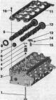
Valve mechanism 1. Valve: cannot be machined, only lapping is allowed; mark mont. reinstallation position. 2. Cylinder head. 3. Valve stem seal. 4. Valve...
Valve mechanism 1. Valve: cannot be machined, only lapping is allowed; mark mont. reinstallation position. 2. Cylinder head. 3. Valve stem seal. 4. Valve...

Lubrication system — replacement of pump and balance shafts
Oil sump, oil pump, balance shaft block 1. Sealing cuff: replace. 2. Oil drain plug: 30 Nm. 3. Oil pan. 4. Bolt: 9 Nm. 5. Suction line: if dirty, clean the...
Oil sump, oil pump, balance shaft block 1. Sealing cuff: replace. 2. Oil drain plug: 30 Nm. 3. Oil pan. 4. Bolt: 9 Nm. 5. Suction line: if dirty, clean the...

Lubrication System — Oil Filter Holder and Oil Cooler
Oil holder. filters and oil radiator 1. Cover: 25 Nm. 2-4. O-ring: replace. 5. Oil element. filter: Follow the instructions. 6. Oil radiator: follow the...
Oil holder. filters and oil radiator 1. Cover: 25 Nm. 2-4. O-ring: replace. 5. Oil element. filter: Follow the instructions. 6. Oil radiator: follow the...

Cooling system — coolant hose connection diagram
Coolant hose connection diagram Cars without independent heater Blue = large coolant circuit. Red = small coolant circuit. Brown = heating circuit. Orange =...
Coolant hose connection diagram Cars without independent heater Blue = large coolant circuit. Red = small coolant circuit. Brown = heating circuit. Orange =...

Cooling system — coolant pump and 4/2-way valve with thermostat
Coolant pump and 4/2-way valve with thermostat 1. Coolant pump 2. Bolt: 15Nm. 3/4. O-ring: replace. 5. 4/2-way valve with thermostat: The thermostat is located...
Coolant pump and 4/2-way valve with thermostat 1. Coolant pump 2. Bolt: 15Nm. 3/4. O-ring: replace. 5. 4/2-way valve with thermostat: The thermostat is located...

Cooling system — coolant pipes, coolant temperature sensor, coolant circulation pump
Coolant pipes, coolant temperature sensor, coolant circulation pump 1. Bolt: 9 Nm. 2. Left lower tube of the system. cooling. 3. O-ring seal: Replace. 4....
Coolant pipes, coolant temperature sensor, coolant circulation pump 1. Bolt: 9 Nm. 2. Left lower tube of the system. cooling. 3. O-ring seal: Replace. 4....
Cooling system — radiator and radiator fan
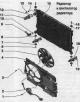
Radiator and radiator fan 1. Bolt: 4.5 Nm. 2. Fan control unit "J293". 3. Bolt: 5 Nm. 4. Fan frame. 5. Radiator fan "V7". 6. Bolt: 3.5 Nm. 7. Lining. 8. Rubber...
Radiator and radiator fan 1. Bolt: 4.5 Nm. 2. Fan control unit "J293". 3. Bolt: 5 Nm. 4. Fan frame. 5. Radiator fan "V7". 6. Bolt: 3.5 Nm. 7. Lining. 8. Rubber...

Turbocharger — replacement of components
Turbocharger 1. Air duct hose. 2. Pulsation damper. 3. Return oil line. 4. Bolt: 9 Nm. 5. Gasket: replace. 6. Threaded nipple: 40 Nm. 7. Gasket: replace. 8....
Turbocharger 1. Air duct hose. 2. Pulsation damper. 3. Return oil line. 4. Bolt: 9 Nm. 5. Gasket: replace. 6. Threaded nipple: 40 Nm. 7. Gasket: replace. 8....

Fuel injection system — component layout
Overview of installation locations 1. Air flow meter "G70". 2. Air bypass valve. filter "N275": option for the national market. 3. Plug connectors: for lambda...
Overview of installation locations 1. Air flow meter "G70". 2. Air bypass valve. filter "N275": option for the national market. 3. Plug connectors: for lambda...

Fuel injection system — schematic overview of the fuel system
Schematic overview of fuel. syst. Caution! To avoid running the high pressure pump dry (very tight tolerances) and in order to quickly start the engine after...
Schematic overview of fuel. syst. Caution! To avoid running the high pressure pump dry (very tight tolerances) and in order to quickly start the engine after...

Injection system — intake manifold
Intake manifold 1. Guide tube: for oil dipstick. 2. Sealing cuff: replace. 3. Gasket: replace. 4. Bolt: 8 Nm. 5. Reverse fuel. highway: the image does not...
Intake manifold 1. Guide tube: for oil dipstick. 2. Sealing cuff: replace. 3. Gasket: replace. 4. Bolt: 8 Nm. 5. Reverse fuel. highway: the image does not...

Injection system — high-pressure fuel pump
High pressure pump 1. Additional holder. units. 2. Bolt: 2 pcs.; replace; 20 Nm +180°. 3. Hub: use the counter support "T10051" for loosening and tightening;...
High pressure pump 1. Additional holder. units. 2. Bolt: 2 pcs.; replace; 20 Nm +180°. 3. Hub: use the counter support "T10051" for loosening and tightening;...

Injection system — injectors
Injection nozzles Caution! When installing a new engine, after installing the high-pressure lines, tighten the injector clamps to the specified torque. To...
Injection nozzles Caution! When installing a new engine, after installing the high-pressure lines, tighten the injector clamps to the specified torque. To...

Exhaust system — diesel particulate filter and exhaust manifold
Removal and installation the diesel particulate filter Remove the exhaust pipe. Unscrew the exhaust gas temperature sensor 4 "G648" "pos. 1". Remove the right...
Removal and installation the diesel particulate filter Remove the exhaust pipe. Unscrew the exhaust gas temperature sensor 4 "G648" "pos. 1". Remove the right...

Exhaust system — exhaust gas temperature sensor
Exhaust gas temperature sensor 1. Turbocharger. 2. Lambda probe "G39" with lambda probe heating element "Z19". 3. Exhaust gas temperature sensor 3 "G495": the...
Exhaust gas temperature sensor 1. Turbocharger. 2. Lambda probe "G39" with lambda probe heating element "Z19". 3. Exhaust gas temperature sensor 3 "G495": the...

Exhaust system — exhaust gas recirculation system
Exhaust gas recirculation system 1. Gasket: replace. 2. Bolt: 9 Nm. 3. EGR pipe. 4. Bolt: 9 Nm. 5. Gasket: replace. 6. Bolt: 9 Nm. 7. Cooling system hose. 8....
Exhaust gas recirculation system 1. Gasket: replace. 2. Bolt: 9 Nm. 3. EGR pipe. 4. Bolt: 9 Nm. 5. Gasket: replace. 6. Bolt: 9 Nm. 7. Cooling system hose. 8....

Checking the preheating device
The control unit for automatic glow plug timing "J179" is located in the relay and fuse box in the switch. block in the water drainage box. A. Automatic glow...
The control unit for automatic glow plug timing "J179" is located in the relay and fuse box in the switch. block in the water drainage box. A. Automatic glow...
This section is available on russian, bulgarian, belarusian, ukrainian, serbian, croatian, romanian, polish, slovak, hungarian
Similar sections of other Audi car models:
Power unit: Diesel fuel system Audi 80 B4 (1991-1996)
Power unit: Diesel engine Audi 100 C3 (1982-1990)
General information: Maintenance (Diesel) Audi A6 C4 (1994-1997)
Power unit: Diesel engine 3.3L Audi A8 D2 (1994-2002)
Power unit: Fuel system (diesel) Audi Q5 Type 8R (2008-2017)
Power unit: Diesel fuel system Audi 80 B4 (1991-1996)
Power unit: Diesel engine Audi 100 C3 (1982-1990)
General information: Maintenance (Diesel) Audi A6 C4 (1994-1997)
Power unit: Diesel engine 3.3L Audi A8 D2 (1994-2002)
Power unit: Fuel system (diesel) Audi Q5 Type 8R (2008-2017)
Share information:
- General information
- Operating instructions
- Power unit
- Petrol engines 1.8 l
- Petrol engines 1.8/2.0 l
- Petrol engines 3.0 l
- Petrol engines 3.2 l
- Fuel system (petrol)
- Diesel engines 2.0 l (CA*)
- Diesel engines 2.0 l (CJCB)
- Diesel engines 2.7/3.0 l
- Diesel engines 3.0 l
- Fuel system (diesel)
- Transmission
- Manual gearbox 0B1
- Manual gearbox 0B2
- Manual gearbox 0B3
- Manual gearbox 0B4
- Automatic transmission 0B5
- Automatic transmission 0B6
- Automatic transmission 0AW
- All-wheel drive system
- Chassis
- Front suspension
- Rear suspension
- Brake system
- Steering system
- Body
- Exterior
- Interior
- Seats
- Doors, locks and windows
- Security system
- Heating and air conditioning
- Electrical equipment
- Audio system
- Power devices
- Equipment and devices
- Lighting and lamps
- Electrical circuits
- General information
- Introduction to manual
- Troubleshooting
- Operating instructions
- Maintenance
- Power unit
- Petrol engines 2.0 (ALT)
- Petrol engines 2.0 (TFSI)
- Petrol engines 1.8 (MPI)
- Diesel engines
- Cooling system
- Air conditioner
- Fuel and exhaust system
- Ignition system
- Starting and charging
- Transmission
- Clutch
- Manual gearbox
- Automatic gearbox
- Drive shafts
- Chassis
- Brake system
- Front suspension
- Rear suspension
- Steering
- Body
- Exterior
- Interior
- Electrical equipment
- Equipment and devices
- Lighting and signaling
- Windscreen wipers and washers
- Electrical diagrams
- Electrical diagrams (since 2007)
- General information
- Vehicle Description
- User manual
- Maintenance
- Power unit
- Gasoline engine
- Diesel engine
- Lubrication system
- Cooling system
- Supply system
- Injection system
- Exhaust system
- Ignition and control
- Transmission
- Gear box
- Clutch and drive shafts
- Chassis
- Brake system
- Car suspension
- Steering
- Body
- Heating and ventilation
- Exterior (external elements)
- Interior (internal elements)
- Electrical equipment
- Power devices
- Lighting and appliances
- Electrical circuits
- General information
- Introduction to the guide
- Car care
- Power unit
- Engine repair
- Lubrication system
- Cooling system
- Injection and control system
- Ignition system
- Power and exhaust system
- Transmission
- Clutch and drive shafts
- Car gearbox
- Chassis
- Suspension and wheels
- Steering
- Brake system
- Body
- Interior
- Exterior
- Electrical equipment
- Equipment and devices
- Lighting and signaling
- Power devices
- Electrical circuits
- General information
- Introduction to the guide
- Car care
- Maintenance (gasoline)
- Maintenance (diesel)
- Power unit
- Gasoline engines
- Diesel engines
- Engine overhaul
- Cooling system
- Fuel injection (gasoline)
- Fuel system (diesel)
- Exhaust system
- Ignition system
- Transmission
- Clutch
- Mechanical gearbox
- Automatic gearbox
- Drive shafts
- Chassis
- Brake system
- Car suspension
- Steering
- Body
- Exterior
- Interior
- Doors, locks and windows
- Heating and ventilation
- Electrical equipment
- Power devices
- Equipment and devices
- Electrical circuits
- General information
- Vehicle description
- Maintenance
- Power unit
- Engine repair
- Turbocharging
- Exhaust system
- Cooling system
- Ignition system
- Fuel system
- Motronic injection system
- MPI and MPFI injection system
- Transmission
- Clutch
- Gearbox and shafts
- Chassis
- Steering
- Car suspension
- Brake system
- Wheels and tires
- Body
- Heating and ventilation
- Body parts
- Electrical equipment
- Fuses and relays
- Power devices
- Lighting and lamps
- Tools and devices
- Electrical circuits