
Table of contents: Injection nozzles ↓ Removal and installation the fuel… ↓
Injection nozzles
Caution! When installing a new engine, after installing the high-pressure lines, tighten the injector clamps to the specified torque. To align the injectors when installing high-pressure lines, tighten the clamps only by hand. Failure to do so can result in engine damage.
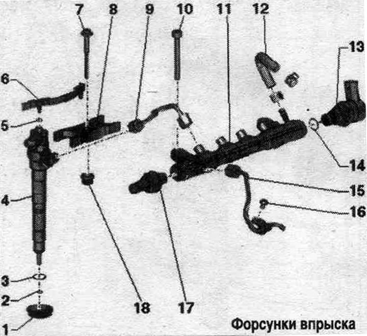
1. Sealing cuff: in the cylinder head cover.
2. Copper seal. ring: replace.
3. Sealing ring: replace.
4. Injector: When reinstalling removed injectors, high-pressure lines and clamps, install them only on the cylinder from which they were removed.
5. Sealing ring: replace.
6. Reverse fuel. main line: to the fuel tank; with throttle valve; should not be bent, damaged or clogged; do not disassemble; the function of the throttle valve is to maintain residual pressure in the return fuel. highways; this control quantity is needed for the injectors to function; after replacement, let the engine idle for two minutes to remove air from the fuel. system and then check the return fuel lines for leaks. highways.
7. Bolt: replace; 8 Nm + 180°.
8. Clamping bracket: For reinstallation, mark the conformity, and observe the marking when installing.
9. High pressure line: between the fuel distributor and the injectors; install freely; lubricate the threads of the union nuts with clean oil; 25 Nm.
10. Bolt: 22 Nm.
11. Fuel distributor.
12. Reverse fuel. hose.
13. Fuel pressure regulating valve "N276": replace after each dismantling; 80 Nm; after replacing the high-pressure pump or the fuel pressure regulating valve "N276", it is necessary to carry out re-adaptation.
14. Sealing ring: replace.
15. High pressure line: between the high pressure pump and the fuel distributor; install freely; lubricate the threads of the union nuts with clean oil; 25 Nm.
16. Bolt: 8 Nm.
17. Fuel pressure sensor "G247": 100 Nm.
18. Nozzle: in the cylinder head cover.
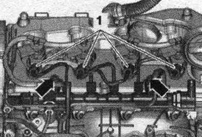
Mounting position of the clamping bracket
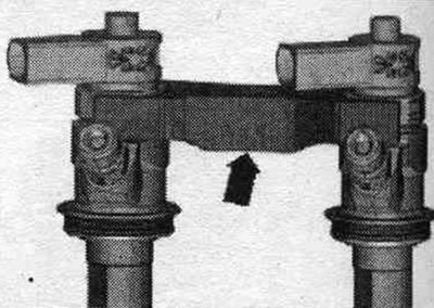
Each clamp covers two injectors. The "arrow" on the clamp faces downward.
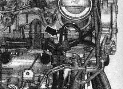
Removal and installation the fuel distributor
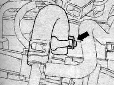
Remove the engine cover. Disconnect the plug connection "arrow" of the fuel pressure regulating valve "N276".
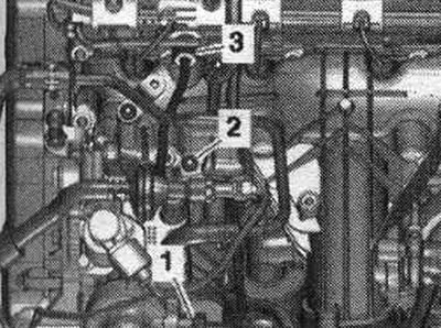
Unscrew bolt "2" and union nuts "1 and 3", remove the high pressure line.
Remove the return fuel. hose from the fuel distributor by loosening the "arrow" hose clamp. Close the open return fuel valve. hose with a clean plug.
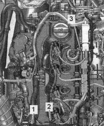
Remove and release vacuum hose "3". Ignore "Pos. 1, 2". Disconnect the glow plug connectors.
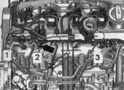
Disconnect plug connections "1, 2, 3". Unscrew the "arrow" bolt, release and set aside the guide with the bundle of wires. Loosen the union nuts securing the high-pressure lines using the "T40055" attachment.
Unscrew the union nuts "1" and bolts "arrows", remove the fuel distributor. Place the removed fuel distributor with high-pressure lines on a clean rag. Close the open holes of the fuel distributor with a clean plug.
Installation
Installation in reverse order: install high pressure lines without stress.