
Overview of installation locations

1. Air flow meter "G70".
2. Air bypass valve. filter "N275": option for the national market.
3. Plug connectors: for lambda probe "G39", for exhaust gas temperature sensor 3 "G495".
4. Lambda probe "G39" with lambda probe heating element "Z19".
5. Execution electric motor system. exhaust gas recirculation "V338" with system potentiometer. eGR "G212": built into the radiator system. exhaust gas recirculation.
6. Exhaust gas temperature sensor 3 "G495".
7. Radiator outlet coolant temperature sensor "G83".
8. Differential pressure sensor "G505".
9. Coolant circulation pump "V50": only for vehicles with start-stop system.
10. Exhaust gas temperature sensor 4 "G648".
11. Coolant temperature sensor "G62".
12. Fuel pressure regulating valve "N276".
13. Gearbox neutral position sensor "G701": only vehicles with start-stop system.
14. Brake booster pressure sensor "G294".
15. Accelerator pedal position sensor "G79" and accelerator pedal position sensor 2 "G185".
16. Brake light switch "F" and brake pedal sensor "F47".
17. Clutch pedal position sensor "G476": with clutch pedal position sensor for engine starting "F194" and clutch pedal switch "F36"; only in cars with manual transmission.
18. Engine control unit "J623".
19. Engine speed sensor "G28".
20. Radiator pump system. exhaust gas recirculation "V400".
21. Throttle control module "J338" with throttle potentiometer "G69".
22. Left el. mag. electric valve. hydr., engine mounts "N144": left only.
23. Boost pressure sensor "G31"/intake air temperature sensor "G42".
24. Fuel temperature sensor "G81".
25. Fuel metering valve "N290".
26. Glow plugs: Glow plug 1 "Q10". Glow plug 2 "Q11". Glow plug 3 "Q12". Glow plug 4 "Q13".
27. Fuel pressure sensor "G247".
28. Hall sensor "G40".
29. Injectors: Injector cyl. 1 "N30". Cyl. injector. 2 "N31". Cyl. injector. 3 "N32". Cyl. injector. 4 "N33".
30. Electromagnetic boost pressure limiting valve "N75".
31. Radiator changeover valve system. exhaust gas recirculation "N345".
32. Boost pressure regulator position sensor "G581".
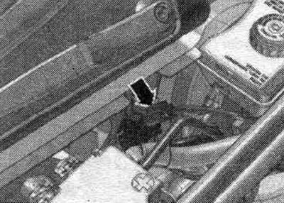
Installation location of the engine control unit "J623"
In the switch block on the left in the water drainage box.
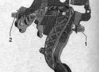
Installation location of the gas pedal position sensor "G79" and gas pedal position sensor 2 "G185"
In the gas pedal module. The accelerator pedal position sensor "G79" and the accelerator pedal position sensor 2 "G185" are integrated into the accelerator pedal module and cannot be replaced separately.
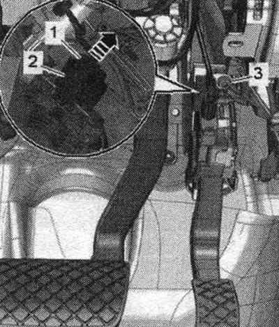
Installation location of the brake light switch "F" and the brake pedal sensor "F47"/clutch pedal position sensor "G476"
1. Brake light switch "F" and brake pedal sensor "F47". 2. Clutch pedal position sensor "G476" with clutch pedal position sensor for engine start "F194" and clutch pedal position sensor "F36" (only in vehicles with manual transmission).
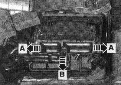
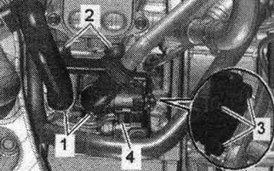
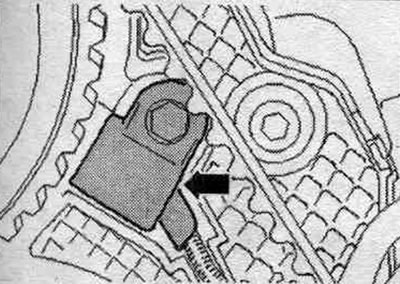
Installation locations
1. Fuel pressure sensor "G247". 2. Fuel temperature sensor "G81". 3. Fuel pressure regulating valve "N276".
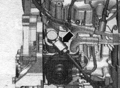
Fuel metering valve "N290" "arrow"
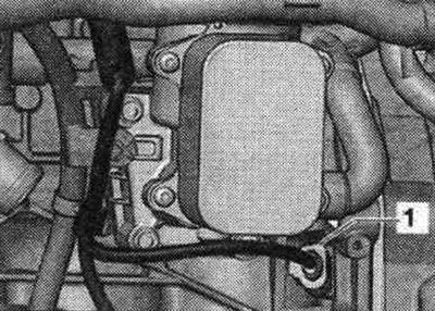
Installation location of the pump for the exhaust gas recirculation cooler "V400"
4. Electrical plug connection of the radiator pump system. exhaust gas recirculation "V400"
On the rear left side of the engine
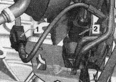
Installation location of the coolant temperature sensor "G62".
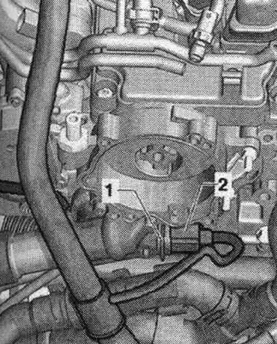
2. Electrical plug connection of the coolant temperature sensor "G62".
On the back of the engine
Installation location of the coolant temperature sensor at the radiator outlet "G83"
"Pos. 1" in the coolant pipe at the rear.
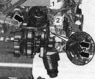
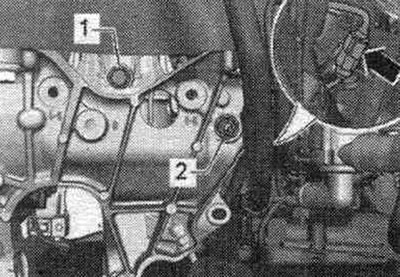
Installation location of the Hall sensor "G40"
At the front of the engine, next to the camshaft timing belt gear, there is an "arrow".
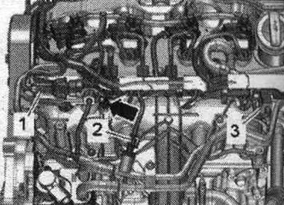
Installation locations
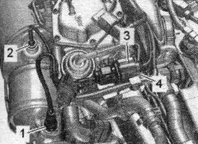
1. Lambda probe "G39". 2. Exhaust gas temperature sensor 3 "G495". 3. Electrical plug connection of the lambda probe "G39". 4. Electrical plug connection of the exhaust gas temperature sensor 3 "G495".
Installation location of the differential pressure sensor "G505"
On the back of the engine.
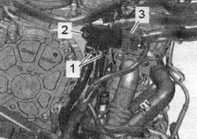
3. Electrical plug connection of the differential pressure sensor "G505".
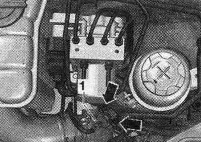
Installation location of the engine speed sensor "G28"
1. Plug connector of the engine speed sensor "G28".
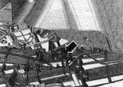
Installation location of the boost pressure sensor "G31" with the intake air temperature sensor "G42"
Front left in motorcycle. compartment.
1. Electrical plug connection of the boost pressure sensor "G31" with the intake air temperature sensor "G42"
Installation location of the boost pressure regulator position sensor "G581"
The turbocharger is on the right side of the engine.
1. Electrical plug connection of the boost pressure regulator position sensor "G581".
Place of installation of el. magnetic boost pressure limiting valve "N75"
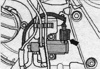
On the front right side of the engine there is an arrow.
Installation location of the neutral position sensor "G701"
On the left side of the gearbox is a "arrow." Only installed on vehicles with a start-stop system.
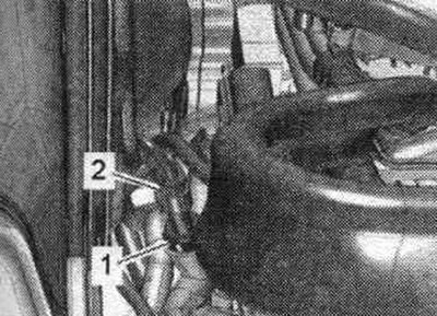
Electrical plug connections
1. Sensor 1 of the exhaust gas temperature "G235". 2. Changeover valve of the radiator system. exhaust gas recirculation "N345".
Place of installation of el. magnetic valve left el. hydr., engine mounts "N144"
On the left engine mount "arrow" (plug connection).
Installation location of the brake booster pressure sensor "G294"
In the vacuum line to the brake booster there is an arrow.