
Turbocharger
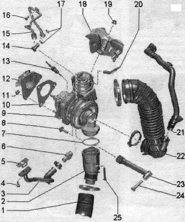
1. Air duct hose.
2. Pulsation damper.
3. Return oil line.
4. Bolt: 9 Nm.
5. Gasket: replace.
6. Threaded nipple: 40 Nm.
7. Gasket: replace.
8. Bolt: 20 Nm.
9. Turbocharger: can only be replaced together with the vacuum drive.
10. Gasket: replace.
11. Nut: replace; lubricate the threads with heat-resistant paste: 24 Nm.
12. Diesel particulate filter.
13. Exhaust gas temperature sensor 1 "G235".
14. Hollow bolt: 30 Nm.
15. Oil supply line: check for patency; before installing the turbocharger, fill the oil supply line nipple with oil; tighten the union nuts to a torque of 22 Nm.
16. Bolt: 9 Nm.
17. Sealing rings: replace.
18. Exhaust manifold.
19. Nut: replace; lubricate the threads with heat-resistant paste; 24 Nm.
20. Vacuum hose.
21. Hose: crankcase ventilation; equipment option for countries with cold climates: with a resistive heating element system. crankcase ventilation "N79".
22. Air guide tube.
23. Turbocharger support.
24. Bolt: 40 Nm.
25. Bolt: 9 Nm.
Vacuum hose connection diagram
When laying vacuum hoses, avoid kinking, twisting or pinching them.
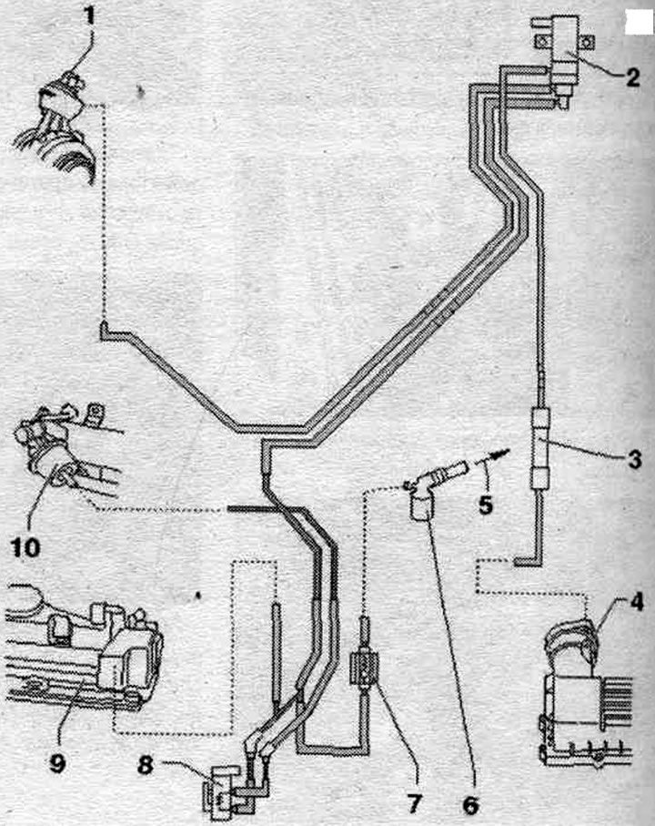
1. Vacuum reservoir on turbocharger: with wastegate position sensor "G581".
2. Electromagnetic boost pressure limiting valve "N75".
3. Soundproofing.
4. Air filter housing.
5. To the brake booster. drive.
6. Adapter: to the vacuum pump.
7. Check valve: Install in the proper position.
8. Radiator changeover valve system. exhaust gas recirculation "N345".
9. Cylinder head cover.
10. Vacuum reservoir: radiator changeover valve system. exhaust gas recirculation.
Removal and installation a turbocharger
Caution! If the turbocharger has mechanical damage (for example, damage to the impeller), it is not enough to simply replace the turbocharger. To prevent further damage, the following steps must be taken. Check the housing and air filter element. filters, as well as air supply hoses, to ensure there is no contamination. Check the entire system. supply air and intercooler for the absence of foreign objects. If in the system. if foreign objects are detected in the air boost line, clean the air boost lines and replace the intercooler if necessary.
Remove the exhaust pipe. Remove the "arrow" engine cover. Remove the air intake housing. filter.
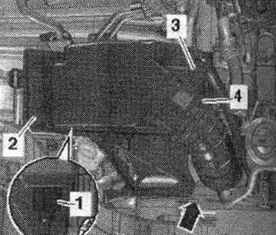
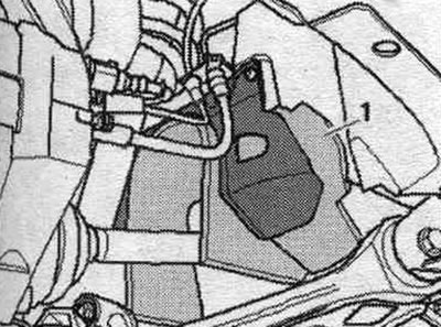
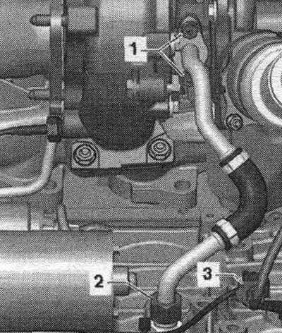
Disconnect the engine crankcase ventilation hose "2" and release it by pressing the release buttons. Remove the air duct hose by loosening the hose clamp "1". Remove the front right wheel.
Remove cover "1" of the drive shaft in the right wheel arch.
Unscrew bolt "2" of the diesel particulate filter suspension. "Pos. 1" should not be taken into account.
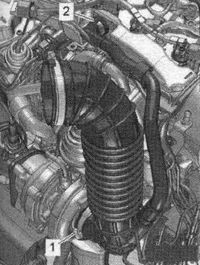
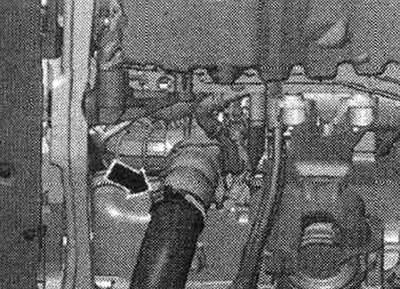
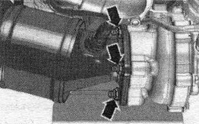
Remove the air duct hose and push it to the side; to do this, loosen the "arrow" clamp.
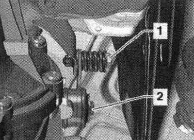
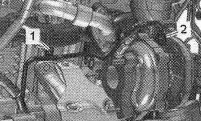
Unscrew bolts "1" and "2", remove the turbocharger support.
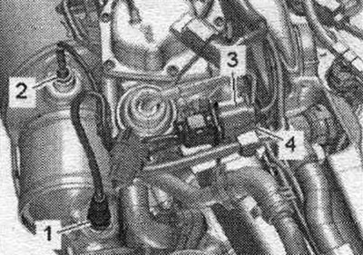
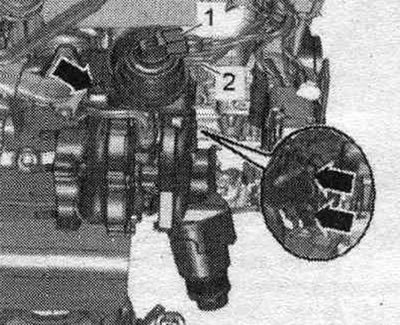
Unscrew the union nut "2". Remove the plug connection "3" of the exhaust gas temperature sensor 1 "G235" from the holder and disconnect it, releasing the wire. "Pos. 1" should not be taken into account.
Unscrew the temperature sensor. OG 4 "G648" "pos. 1".
Disconnect and release plug connection "4". Remove lambda probe "1".
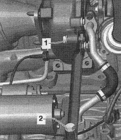
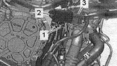
Unscrew bolt "2" and release hoses "1" on the bracket. Place the differential pressure sensor "G505" back.
Unscrew the arrow nuts and remove the diesel particulate filter back.
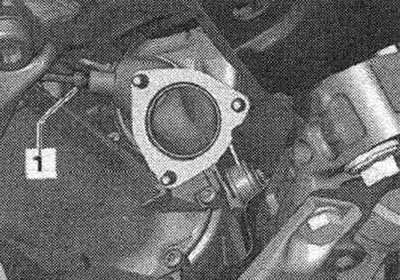
Unscrew union nut "2". Ignore "Pos. 1".
Disconnect plug connection "1". Remove vacuum hose "2". Unscrew the "arrow" nuts and remove the blower. Close open lines and pipes with clean plugs from the VAS 6122 engine plug kit.
Installation
Installation in reverse order. Replace the gasket, nuts and O-ring. Fill the turbocharger with oil through the oil supply line nipple. To ensure that oil is supplied to the turbocharger, the engine must be run for approx. 1 minute at idle speed; do not give the engine high revs. Install a diesel particulate filter. Install the front noise insulation screen. Install the air casing. filter. Connect the air duct hoses using threaded clamps.
The original version is on the portal AUDIMANUAL