



Table of contents: Removal ↓ Installation ↓
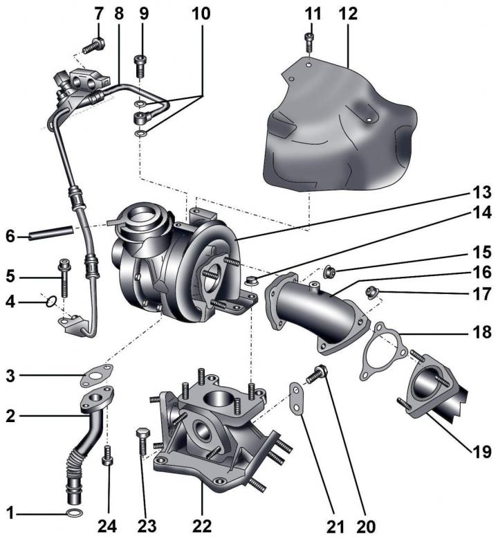
Fig. 5.3–2. Turbocharger: 1 – sealing ring; 2 – oil return pipe to the cylinder block; 3 – gasket; 4 – sealing ring; 5 – bolt, 10 Nm; 6 – hose to the vacuum chamber to control the pressure increase; 7 – bolt, 22 Nm; 8 – oil supply pipe from the oil filter bracket; 9 – hollow bolt, 15 Nm; 10 – sealing rings; 11 – bolt, 10 Nm; 12 – heat shield; 13 – turbocharger; 14 – nut, 22 Nm; 15 – nut, 22 Nm; 16 – exhaust manifold elbow for turbocharger mounting; 17 – bolt, 25 Nm; 18 – gasket; 19 – exhaust pipe with neutralizer; 20 – bolt, 22 Nm; 21 – rack for intermediate transition element; 22 – transition element; 23 – bolt, 22 Nm; 24 – bolt, 10 Nm
The power that an engine can develop depends on the amount of air and fuel that enters the engine cylinders. To increase engine power, it is necessary to increase the supply of air and fuel. Supplying more fuel will not have an effect until there is enough air for combustion. Otherwise, an excess of unburned fuel is formed, which leads to overheating and increased smoke in the engine. To increase the amount of air supplied to the engine, a turbocharger is used, which compresses the air entering the combustion chamber (Fig. 5.3–2).
The turbocharger consists of a centrifugal compressor wheel and a turbine connected by a common rigid axis. Both of these elements rotate in the same direction at the same speed. The energy of the exhaust gas flow, which is not used in conventional engines, is converted into torque, which drives the turbocharger. The exhaust gases leaving the engine cylinders have high temperature and pressure. They are accelerated to high speed and interact with the turbine blades, which converts kinetic energy into mechanical rotational energy. The conversion of energy is accompanied by a decrease in the temperature and pressure of the exhaust gases. The turbocharger sucks in air through the air filter, compresses it and feeds it into the engine cylinders. The amount of fuel that can be mixed with air can be increased, which allows the engine to develop more power.
For turbocharger lubrication motor oil is supplied under pressure through a special pipeline.
Since the turbocharger operates at high speed, care and cleanliness must be taken: dirt entering the turbocharger can cause it to fail.
Warning: Before disconnecting any components from the turbocharger, thoroughly clean them from dirt. To protect against dirt, place the components removed from the turbocharger in a sealed container, close the air ducts of the turbocharger.
An air-to-air intercooler is installed between the turbocharger and the intake manifold, which reduces the temperature of the air supplied to the engine. Cooling the air increases engine power, since the oxygen content in cold air increases due to its higher density.
Note: The vacuum reservoir is located at the front of the vehicle under the wheel arch guard.
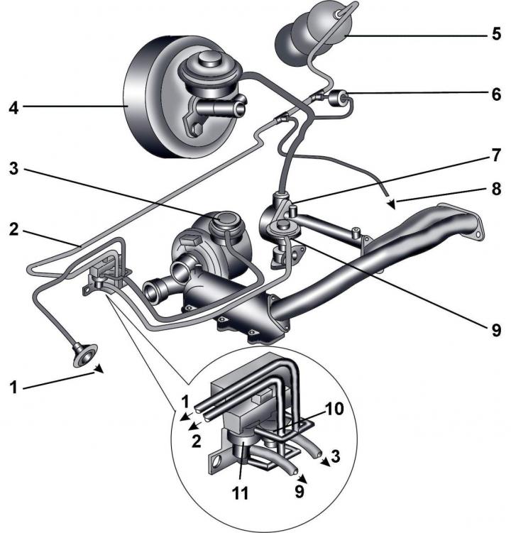
Fig. 5.3–1. Elements of the control system for increasing the pressure of the air entering the engine: 1 – to the breather on the air filter housing; 2 – vacuum hose to vacuum tank or vacuum pump; 3 – vacuum hose from the high pressure solenoid valve; 4 – brake booster; 5 – vacuum tank; 6 – one-way valve; 7 – vacuum pump; 8 – to the intake manifold valve switch N₂39; 9 – vacuum hose from valve N18 to mechanical valve of the exhaust gas recirculation system; 10 – electromagnetic valve for pressure increase control N75; 11 – EGR valve N18
Please pay attention to the installation position (light side/dark side), shown in Fig. 5.3–1.
Removal
Turn off the ignition and disconnect the ground wire from the battery.
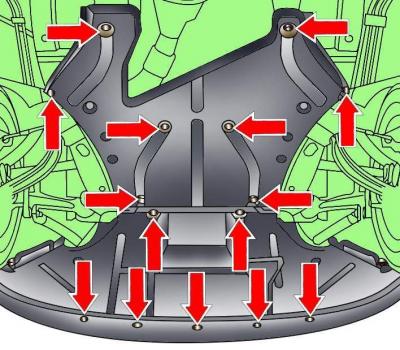
Fig. 5.3–3. Location of the engine compartment lower mudguard mounting fasteners
Release the fasteners and remove the rear section of the lower engine compartment mudguard (Fig. 5.3–3).
Unscrew the bolt securing the exhaust inlet pipe to the adapter.
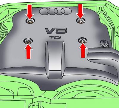
Fig. 5.3–4. Location of engine casing mounting screws
Loosen the screws and remove the engine casing (Fig. 5.3–4).
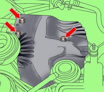
Fig. 5.3–5. Location of heat shield mounting bolts above turbocharger
Unscrew the bolts and remove the heat shield above the turbocharger (Fig. 5.3–5).
Unscrew the bolts securing the exhaust inlet pipe to the turbocharger (Fig. 5.3–6).
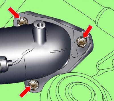
Fig. 5.3–6. Location of bolts securing the exhaust inlet pipe to the turbocharger
Move the exhaust outlet pipe back and down.
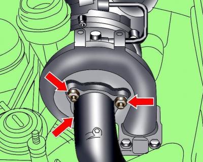
Fig. 5.3–7. Location of exhaust manifold elbow mounting nuts to turbocharger
Unscrew the exhaust manifold elbow mounting nuts from the turbocharger (Fig. 5.3–7).
Loosen the clamps and remove the air duct from the air filter.
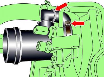
Fig. 5.3–8. Fastening pipes to the turbocharger
Loosen and remove the pipes from the turbocharger (Fig. 5.3–8).
Disconnect the hose from the boost control vacuum chamber.
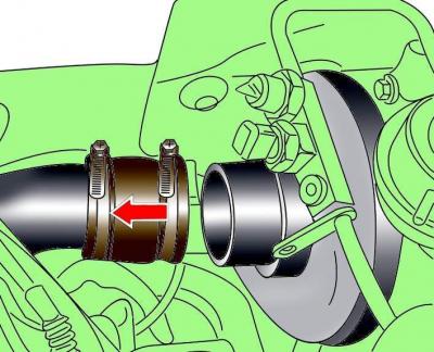
Fig. 5.3–9. Removing the air outlet pipe from the turbocharger
Loosen the clamps, remove and move the air outlet pipe away from the turbocharger (Fig. 5.3–9).
Release the clamps, remove the fuel lines from the oil line bracket and move them to the side.
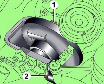
Fig. 5.3–10. Fastening the oil line to the turbocharger (1) and intake manifold (2)
Disconnect the oil line from the turbocharger and intake manifold (Fig. 5.3–10).
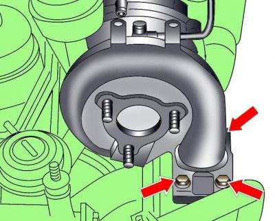
Fig. 5.3–11. Location of turbocharger mounting bolts to transition element
Unscrew the four bolts securing the turbocharger to the adapter and remove the turbocharger (Fig. 5.3–11).
Cover the oil supply hole in the engine block with a clean rag.
Installation
Installation is carried out in the reverse order of removal, taking into account the following.
Replace all O-rings, gaskets and self-locking nuts.
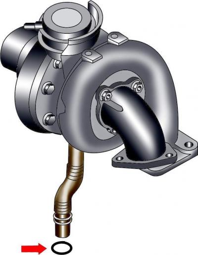
Fig. 5.3–12. Location of the turbocharger oil return pipe sealing ring
Check that the turbocharger oil return pipe sealing ring is not damaged (Fig. 5.3–12).
Fill the turbocharger with oil through the oil feed tube hole.
After installing the turbocharger, start the engine and let it idle for 1 minute, this will ensure reliable lubrication of the turbocharger.
Check the engine oil level.
(Material republished from the website audimanual.ru)