
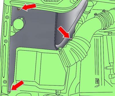
Fig. 5.1–4. Location of fuel filter housing mounting screws
Remove the cover from the right side of the engine compartment (Fig. 5.1–4).
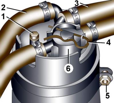
Fig. 5.1–5. Fuel filter fastening elements: 1 – plug, 4 N·m; 2, 3 – fuel supply hoses; 4 – spring clamp; 5 – nut; 6 – control valve
Pull and remove spring clip 4 securing control valve 6 (Fig. 5.1–5).
Remove the control valve together with the connected pipes.
Loosen the clamps and remove fuel supply hoses 2 and 3 from the fuel filter fittings.
Loosen nut 5 of the bracket and remove the fuel filter.
Place the plastic mounting sleeve onto the new fuel filter.
Install the fuel filter into the bracket and secure the bracket clamp with a nut. The direction of fuel flow is indicated by an arrow on the filter.
Fill the new fuel filter with clean diesel fuel to ensure fast engine start.
Install the sealing ring and adjusting valve in place and secure them with the spring clip.
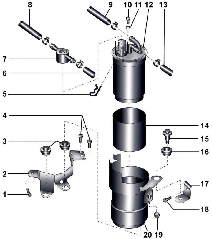
Fig. 5.1–3. Fuel filter: 1 – bolt, 10 Nm; 2 – fuel filter bracket; 3 – rubber sealing rings; 4 – bolts, 10 Nm; 5 – spring clamp; 6 – fuel return pipe from the fuel pump; 7 – control valve; 8 – fuel return pipe to the fuel tank; 9 – fuel supply pipe from the fuel tank; 10 – plug, 4 Nm; 11 – gasket; 12 – fuel filter; 13 – fuel supply pipe to the fuel pump; 14 – mounting sleeve; 15 – combination bolt, 10 Nm; 16 – rubber sealing ring; 17 – bracket; 18 – bolt, 10 Nm; 19 – bolt, 10 Nm; 20 – fuel filter bracket
Identical sealing rings 3 and 16 (see Fig. 5.1–3) are installed on the bracket with the funnel-shaped surfaces facing upward.
When installing the regulating valve, the arrow on it should point towards the fuel tank.
Install fuel supply hoses 2 and 3 (see Fig. 5.1–5) onto the fuel filter and secure them with clamps.
Checking the control valve:
- at temperatures below +15°C the valve is open;
- at temperatures above +31°C the valve is closed.
(The original text is available on the website audimanual.ru)