



The elements of the exhaust system are connected by threaded connections or clamps.
In vehicles with diesel engines, an unregulated catalytic oxidation neutralizer is used to reduce the toxicity of exhaust gases.
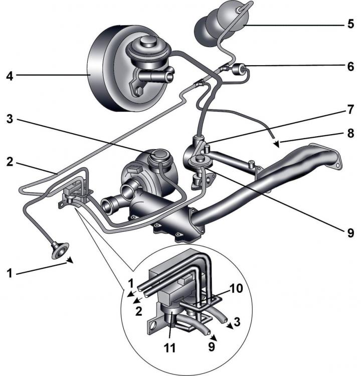
Fig. 5.3–1. Elements of the control system for increasing the pressure of the air entering the engine: 1 – to the breather on the air filter housing; 2 – vacuum hose to vacuum tank or vacuum pump; 3 – vacuum hose from the high pressure solenoid valve; 4 – brake booster; 5 – vacuum tank; 6 – one-way valve; 7 – vacuum pump; 8 – to the intake manifold valve switch N₂39; 9 – vacuum hose from valve N18 to mechanical valve of the exhaust gas recirculation system; 10 – electromagnetic valve for pressure increase control N75; 11 – EGR valve N18
The reduction of nitrogen oxide content in the exhaust gases of a diesel engine is achieved by installing an exhaust gas recirculation (EGR) system on the vehicle. The EGR valve (Fig. 5.3–1) of the recirculation system is installed in the elbow of the exhaust system and is controlled by a vacuum regulator. Through the EGR valve on a warmed-up engine, part of the exhaust gases are directed into the combustion chambers of the engine, as a result of which the temperature decreases and the nitrogen oxide content in the exhaust gases decreases.
Tightening torques, Nm
| Turbocharger to intermediate element | 22 |
| Oil line to intake manifold | 22 |
| Exhaust manifold elbow to turbocharger | 22 |
| Intake exhaust pipe to turbocharger | 25 |
| Intake exhaust pipe with neutralizer to intermediate element | 25 |
| Heat shield for turbocharger | 10 |
[The original version is on the portal: AUDImanual.ru]