
Table of contents: Removal the catalytic converter ↓ Install ↓ Removal the secondary air supply… ↓ Installation ↓
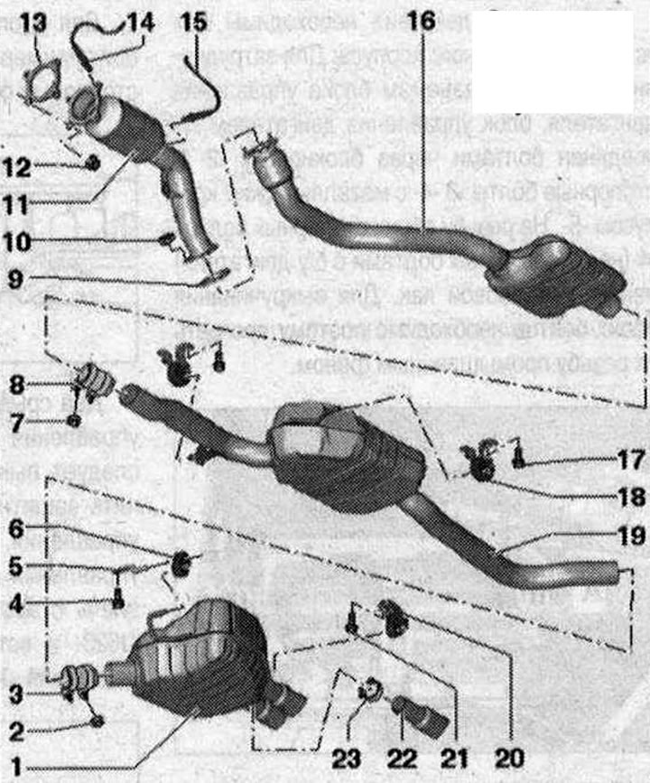
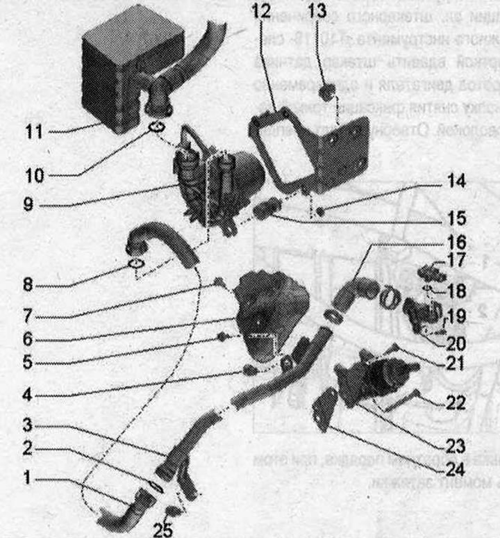
Muffler 1. Main muffler. At the factory, it is installed with the middle muffler as 1 part. In case of repair, it is replaced separately. Align the exhaust system without mechanical stress; 2/7/10. Nut. 25 Nm; 3. Rear clamp. Before tightening, align the exhaust system without mechanical stress. Tighten the threaded connections evenly; 4/17/21. Bolt. 23 Nm; 5. Bracket; 6. Fastening loop. Replace if damaged; 8. Double clamp, front. Before tightening, align the exhaust system without mechanical stress. Tighten threaded connections evenly; 9. Gasket. Replace; 11. Catalyst. Protect the catalytic converter from impacts and jolts. Align the exhaust system without mechanical stress; 12. Nut. 40 Nm. Replace. Lubricate the turbocharger mounting pins with heat-resistant paste; 13. Gasket. Replace; 14. Lambda probe "G39" and heating element of lambda probe "Z19". The threads of new lambda probes are lubricated with mounting paste. When reusing the old lambda probe, lubricate its threads with heat-resistant paste. Mounting and heat-resistant pastes should not get into the grooves of the lambda probe housing; 15. Lambda probe after catalytic converter "G130" and heating element of lambda probe 1 after catalytic converter "Z29". The threads of new lambda probes are lubricated with mounting paste. When reusing the old lambda probe, lubricate its threads with heat-resistant paste. Mounting and heat-resistant pastes must not get into the grooves of the lambda probe housing; 16. Intermediate silencer with split element. Risk of damage to the split element. The split element must not be bent more than 10°. Do not apply traction force to the split element. Do not damage the wire mesh on the split element. Align the exhaust system without mechanical stress; 18. Suspension mount. Replace if damaged. Check pre-tension; 19. Additional muffler. At the factory, it is installed with the main muffler as 1 part. In case of repair, it is replaced separately. Align the exhaust system without mechanical stress; 20. Suspension mount. Replace if damaged. Check pre-tension; 22. Exhaust pipe. Replace separately during repair. Separation point between rear muffler and muffler exhaust pipe; 23. Clamp bracket. 60 Nm
Removal the catalytic converter
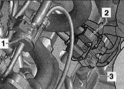
Disconnect electrical connector "1" of the lambda probe after the catalytic converter "G130" and the heating element of the lambda probe 1 after the catalytic converter "Z29" and release the wires. Disconnect electrical connector "2" of the lambda probe "G39" and the heating element of the lambda "probe-Z19" and release the wires.
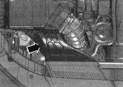
Remove the air duct "arrow".
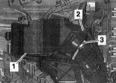
Disconnect the plug connector "2" of the air flow meter "G70". Remove the air duct hose from the air flow meter "G70" by loosening the hose clamp "3". Remove the air filter housing "1" upwards. Remove the sound insulation.
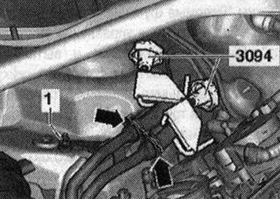
Cars with independent heater: Clamp the independent heater cooling system lines from above with hose clamps up to 25 mm "3094" and disconnect. Unscrew nut "1" of the cooling system lines from the body.
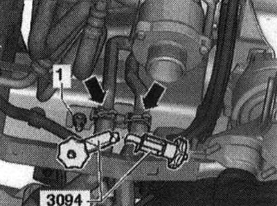
Clamp the cooling system lines of the independent heater from below with clamps for hoses up to 25 mm "3094" and disconnect. Unscrew the cooling system lines "1" from the body and remove.
All
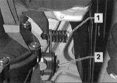
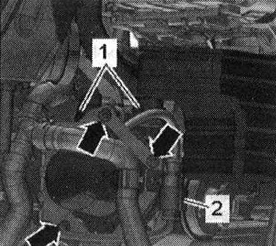
Remove the additional muffler. Disconnect the threaded connection "1", unscrew the bolt "2" and remove the catalytic converter mount.
Unscrew the "arrow" bolts and remove the heat shield of the right drive shaft.
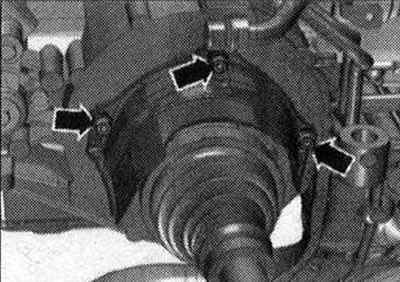
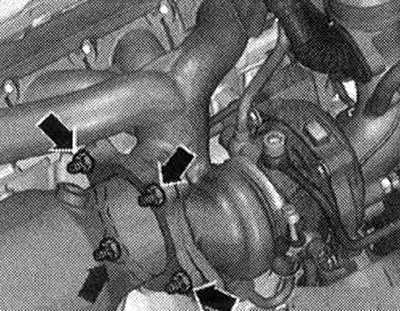
Unscrew the "arrow" nuts and remove the turbocharger upwards.
Install
Installation is in reverse order, taking into account the tightening torques. Replace all cuffs, gaskets and self-locking nuts. Install the front muffler.
Cars with independent heater: Bleed the independent heater.
Secondary air supply system for installation
I 1. Secondary air supply hose; 2. Sealing ring. Replace; 3. Secondary air supply tube; 4. Bolt 20 Nm; 5/7/13/21/22/25. Bolt. 9 Nm; 6. Heat-protective casing; 8. Sealing ring. Replace; 9. Secondary air supply fan motor "V101"; 10. Sealing ring. Replace; 11. Secondary air supply hose with resonator; 12. Bracket of the secondary air supply pump motor "V101"; 14. Nut. 8 Nm; 15. Rubber-metal support; 16. Secondary air supply hose; 17. Secondary air pressure sensor 1 "G609"; 18. Sealing ring. Replace; 19. Bolt. 4 Nm; 20. Support; 23. Secondary air supply control valve "N112"; 24. Gasket. Replace
Removal the secondary air supply pump motor "V101"
Remove the air filter housing. Disconnect connector "2". Disconnect secondary air supply hoses "1", to do this, press the release buttons. Unscrew the nuts "arrows" and remove the secondary air pump motor "V101".
Installation
Installation is in reverse order, observing the tightening torque. Replace the sealing rings. Install the air filter housing.
(The original material is located on the website: AudiManual.ru)