



Table of contents: Upper Oil Pan Tightening Sequence ↓ Oil Separator. Tightening Sequence ↓ Install ↓ Removal the lower part of the oil pan ↓ Install ↓ Removal the oil pump ↓ Install ↓ Removal the top of the oil pan ↓ Install ↓ Removal the engine oil cooler ↓ Install ↓ Checking oil pressure ↓ Installation ↓
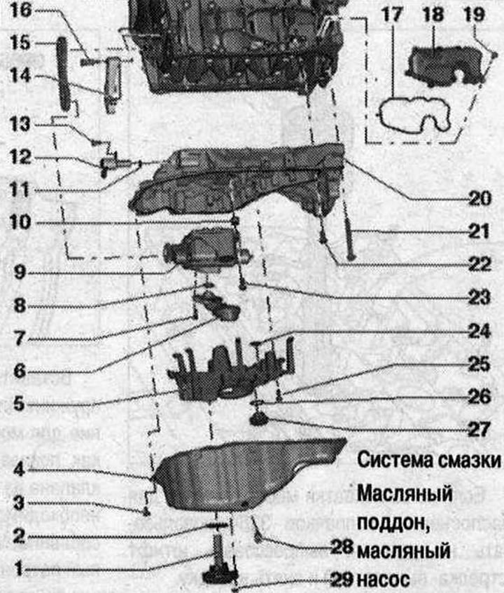
Oil pan, oil pump 1. Oil level and temperature sensor "G266"; 2. Gasket. Replace; 3. Bolt. Replace; 4. Lower part of the oil pan; 5. Oil separator. Replace; 6. Suction pipe. Clean the filter if dirty.; 7. Bolt. 9 Nm; 8. Sealing ring. Replace. Lubricate with oil; 9. Oil pump; 10. Centering sleeve; 11. Sealing ring. Replace; 12. Oil pressure regulating valve "N428"; 13. Bolt. 9 Nm; 14. Chain tensioner; 15. Oil pump drive chain. Before removing, mark the direction of travel; 16. Bolt. 9 Nm; 17. Gasket. Replace; 18. Oil separator; 19. Bolt. Tightening sequence; 20. Upper part of the oil pan; 21/22. Bolt. Replace; 23. Bolt. 20 Nm; 24. Gasket; 25. Bolt. 9 Nm; 26. Gasket; 27. Check valve; 28. Oil drain plug. Replace. 30 Nm; 29. Nut. 9 Nm
Oil pan. Tightening sequence
Tighten bolts "1...19" in 2 stages:
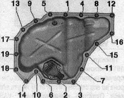
- 1. Tighten the bolts to 8 Nm.
- 2. Tighten the bolts by 45°.
Upper Oil Pan Tightening Sequence
Tighten bolts "1...13" in 2 stages:
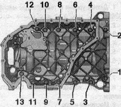
- 1. Tighten the bolts to 15 Nm.
- 2. Tighten the bolts by 90°.
Oil Separator. Tightening Sequence
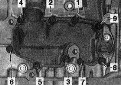
Tighten the bolts in sequence "1...9" to a torque of 9 Nm.
Removing the oil pre-cleaning sump
Support the engine. Loosen the clamps for the "arrow" hose and remove the air duct hose.
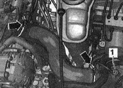
Remove the front left wheel. Remove the sound insulation. Remove the left wheel arch liner. Unscrew bolt "1" of the left engine mount. Remove the left engine support.
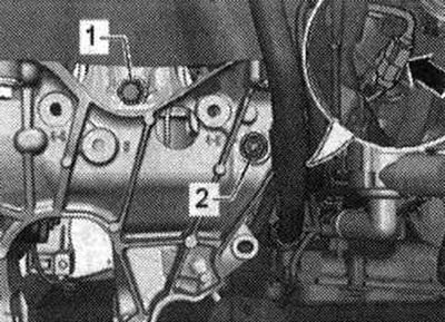
Remove the pre-filter oil sump "1...9".
Install
Installation is in reverse order, taking into account the tightening torques. Install the noise-insulating casing.
Removal the lower part of the oil pan
Remove the sound insulation. Remove the subframe crosspiece "4". Remove the stabilizer "1". Unscrew the bolts "2" and remove the nuts "3". Slightly move the steering gear "5" to the right, lower it by about 10 cm and secure it at the top.
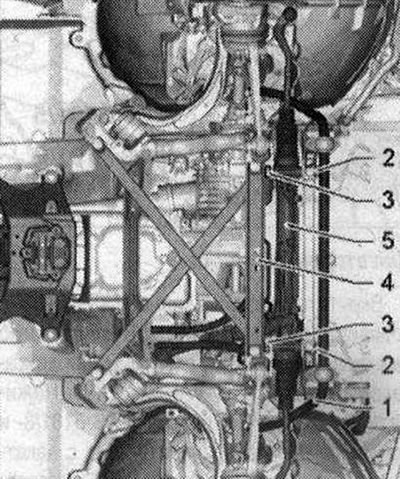
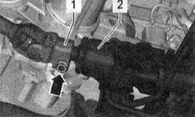
Risk of damage to chassis components. If the powertrain support, steering gear or subframe crosspiece is incorrectly installed, it is prohibited to place the vehicle on its wheels! Using the subframe or subframe crosspiece as a vehicle support (for example, when lifting with a jack or similar device) unacceptable! Unscrew the bolt "arrow". Remove the steering column "1" from the steering gear "2".
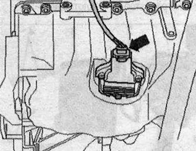
Place an oil drainer under the engine and drain the oil. Remove the connector of the oil level and temperature sensor "G266" "arrow". Remove the engine oil level and temperature sensor "G266".
Bolts "1...19". Remove the oil pan, if necessary, dismantle it by lightly tapping with a rubber hammer.
Install
Observe the expiration date of the silicone sealant. The oil pan must be installed within 5 minutes after applying the silicone sealant. Replace bolts that were tightened with additional tightening. Replace all seals, gaskets and self-locking nuts. Spray the mounting surface with sealant remover and allow time for action. Remove sealant residue on the top of the oil pan with a flat scraper. Remove sealant residue on the oil sump and pan, for example, using a drill with a clamped plastic bristle brush. Clean the mounting surfaces; there should be no oil or grease on them. Cut off the tube tip at the front mark (About 3mm holes). Apply silicone sealant as shown in the figure to the clean sealing surface of the lower part of the oil pan. Sealant strip thickness: 2...3 mm.
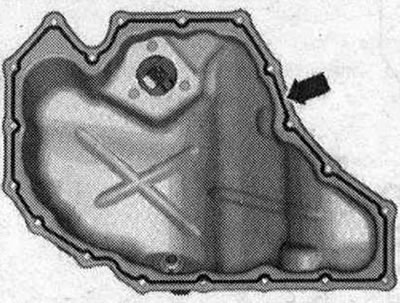
The oil pan must be installed within 5 minutes after applying the silicone sealant. The bead of sealant must not be thicker than the specified width, otherwise excess sealant may get into the oil pan and clog the mesh filter in the oil intake pipe. Install the lower part of the oil pan immediately and tighten the bolts. After installing the oil pan, let the sealant dry for about 30 minutes. Only then can you fill in the oil. Fill in the oil and check its level. Install the steering gear. Install the stabilizer. Install the subframe crosspiece. Install the sound insulation. Install in the reverse order.
Removal the oil pump
Removing the lower part of the oil pan. Remove the oil separator "arrows".
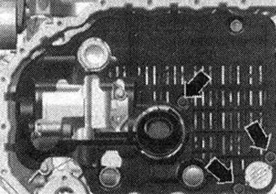
Unscrew the bolts "arrow" and remove the oil pump.
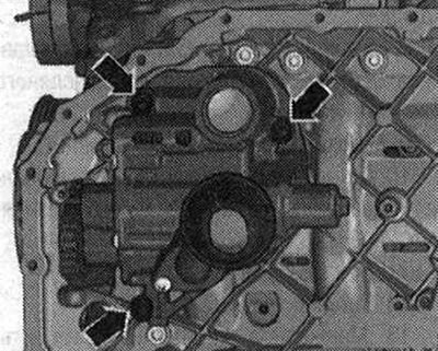
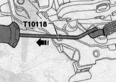
Pull the chain tensioner with the assembly tool "T10118" in the "direction of the arrow" and remove the oil pump with the sprocket.
Install
Installation is in reverse order, taking into account the tightening torques. Replace the oil separator. Check the presence of both installation bushings for centering the oil pump. Install the lower part of the oil pan. Fill with oil and check its level.
Removal the top of the oil pan
Gearbox removed. Removing the lower part of the oil pan. Remove the rear sealing flange. Remove the oil pump. Disconnect the plug connector "1".
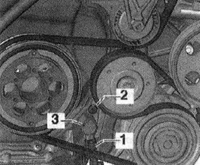
Unscrew the "arrow" bolts.
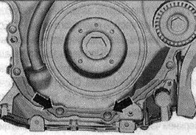
Risk of injury! When removing the upper part of the oil pan, the spring of the oil pump drive chain tensioner bounces off the upper part of the oil pan to the lower timing chain cover. When removing the upper part of the oil pan, do not hold on between the upper part of the oil pan and the lower timing chain cover. Unscrew bolts "1...13" and remove the upper part of the oil pan. First, unfasten the upper part of the oil pan on the gearbox side. When unfastening, proceed carefully to avoid deformation of the timing chain cover.
Install
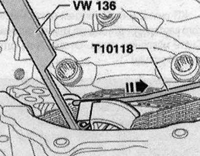
Check the expiration date of the silicone sealant. The upper part of the oil pan must be installed within 5 minutes after applying the silicone sealant. Replace the bolts that were tightened with additional tightening. Replace all cuffs, gaskets and self-locking nuts. Take the assembly device "T10118" and pull the spring of the oil pump drive chain tensioner in the direction of the damper bar "arrow". Fix the spring by inserting the brake lining wear test tool "VW 136" into the hole in the damper bar, as shown in the figure.
Remove any remaining sealant from the cylinder block with a flat scraper. Remove any remaining sealant from the top of the oil pan, e.g. with a drill with a rotating plastic brush attachment. Check that the timing chain cover is not deformed. To do this, first install the top of the oil pump without using sealant and check the gap between the lining and the top of the oil pan. If deformation is detected or the cover cannot be aligned, replace the cover after first installing the top of the oil pan. Clean the seating surfaces; there should be no oil or grease on them. Check the oil channels of the upper part of the oil pan and the cylinder block for contamination. Cut off the tube tip at the front mark (hole diameter about 3mm). Apply silicone sealant as shown in the figure "arrows" to the clean sealing surface of the upper part of the oil pan. Thickness of the sealant strip: 2-3 mm.
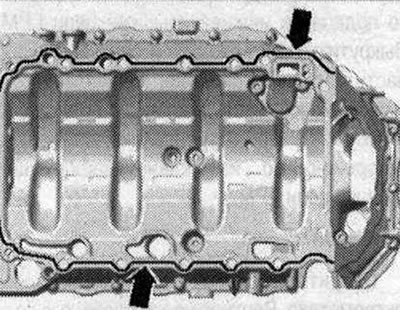
The oil pan must be installed within 5 minutes after applying the silicone sealant. The sealant bead must not be thicker than the specified width, otherwise excess sealant may fall into the oil pan and clog the mesh filter in the oil intake pipe. On the gearbox side, the upper part of the oil pan and the engine crankcase must be flush. Install the upper part of the oil pan immediately and tighten the bolts, tightening sequence. Screw in the bolts "arrows". Remove the tool for checking the wear of the brake linings "VW 136" from the damper bar "arrow".
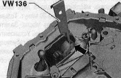
Now the spring returns to the installation position. Install the rear sealing flange. Install the oil pump. Replace the oil separator. Installation in reverse order. Fill with oil and check its level.
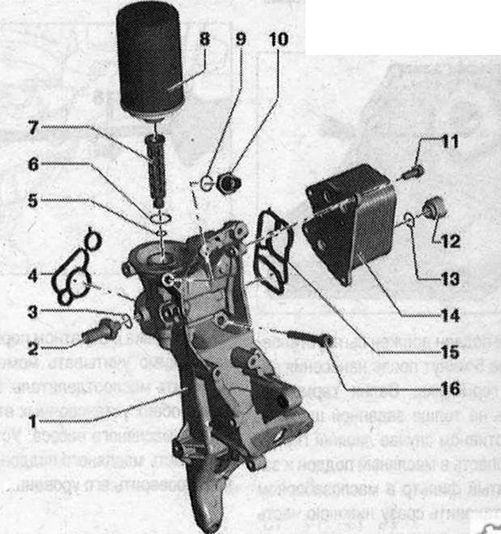
Parts and components of oil filter, oil radiator 1. Additional units bracket; 2. Oil pressure sensor "F22". Blue insulation. 20 Nm; 3. Lip seal. Replace; 4. Gasket. Replace; 5/6. Sealing ring. Not a spare part, included in the scope of delivery of the valve block; 7. Valve block with sealing ring; 8. Oil filter. Remove and install with oil filter wrench "3417"; 9. Lip seal. Replace; 10. Oil pressure sensor for low pressure "F378". Brown insulation. 20 N·m; 11. Bolt. 23 Nm; 12. Connecting pipe; 13. Lip seal. Replace. Moisten with coolant concentrate, coolant; 14. Engine oil cooler. Check for free space with adjacent parts; 15. Gasket. Replace; 16. Bolt
Removal the engine oil cooler
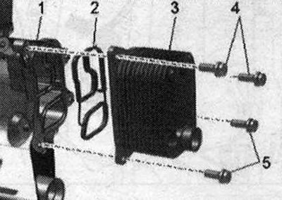
Drain the coolant. Remove the accessory holder. Unscrew bolts "4 and 5" and remove the oil radiator "3" with seal "2".
Install
Installation in reverse order, taking into account the tightening torques. Gaskets and sealing rings must be replaced. Use clamps of the appropriate series to secure all hose connections. Install oil radiator "3" with a new seal "2". Install the bracket for additional units. Fill with coolant. Fill with oil and check its level.
Checking oil pressure
Initial conditions for checking: oil level is normal, check. Engine oil temperature min. 80°C (the radiator fan should complete 1 cycle).
Place a rag under the accessory bracket to collect any escaping oil. Disconnect the electrical plug connection "4" on the low pressure oil pressure sensor "F378". Unscrew the low pressure oil pressure sensor "F378" "3".
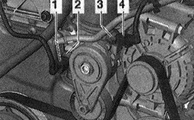
Screw the pressure gauge nipple into place of the sensor in the oil filter bracket. Screw the low pressure oil pressure sensor "F378" into the pressure gauge for measuring oil pressure "V.A.G 1342". Start the engine. Oil pressure at idle: 1.2...2.1 bar excess pressure. Oil pressure at 2000 rpm: 1.6...2.1 bar excess pressure. Oil pressure at 3700 rpm: 3.0...4.0 bar excess pressure. At first, the oil pressure at 2000 rpm may be from 3.0 to 4.0 bar.
Installation
Install the low pressure oil pressure sensor "F378".
The original text of the material can be found on the website AUDIMANUAL