
Table of contents: Upper Timing Chain Cover Tightening… ↓ Lower Chain Drive Cover Tightening… ↓ Removal valve 1 of the variable… ↓ Install ↓ Removal the lower cover of the drive… ↓ Install ↓ Crankshaft Sprocket. Mounting… ↓ Removal the camshaft chain drive ↓ Install ↓ Balance shaft tube. Mounting position ↓ Support pin. Mounting position ↓ Intermediate shaft gear. Tightening… ↓ Tighten the new bolt in the… ↓ Removal the balance shaft chain drive ↓ Install ↓ Checking the timing phases ↓
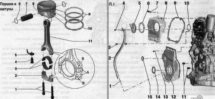
- 1. Sealing ring. Replace. Lubricate before installation
- 2. Oil dipstick guide tube
- 3/4. Bolt. 9 Nm
- 5. Valve 1 for adjusting the timing phases "N₂05"
- 6. Lip seal. Lubricate before installation. Replace if damaged
- 7. Bolt
- 8. Upper chain drive cover
- 9. Gasket. Replace if damaged
- 10. Sealing ring. Replace. Lubricate before installation
- 11. Mounting pins
- 12. Lower drive chain cover. Replace
- 13. Bolt. Replace
- 14. Sealing of the torsional vibration damper shaft
- 15. Plug. Replace
Upper Timing Chain Cover Tightening Sequence
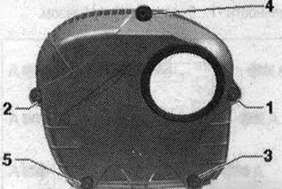
Tighten bolts "1. 5" in the sequence shown in the figure:
1. Tighten the bolts to 9 Nm.
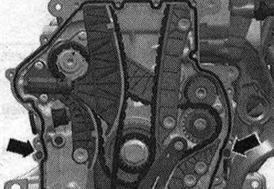
Lower Chain Drive Cover Tightening Sequence
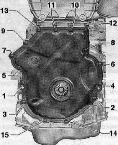
Tighten the bolts "1.15" in 2 stages in the sequence shown in the figure:
1. Tighten the bolts to 8 Nm.
2. Tighten the bolts by 45°.
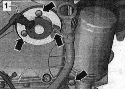
Removal valve 1 of the variable valve timing system "I205"
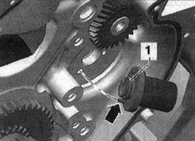
Disconnect the connector of valve 1 of the variable valve timing system "N₂05" "1". Unscrew the "arrow" bolts and remove valve 1 of the timing phase change system "N₂05".
Install
Installation is in reverse order, in this case it is necessary to replace the sealing ring. Lubricate the sealing cuff and sealing ring with oil.
Removal the lower cover of the drive chain
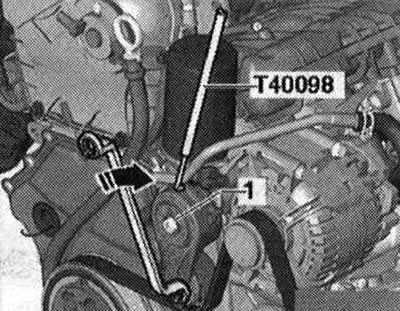
Remove the front noise insulation. Remove the front bumper trim and bumper. Bring to the service position. To loosen the poly V-belt, turn the tensioner in the "direction of the arrow". Secure the tensioner with the "T40098" lock. Unscrew bolt "1" and remove the poly V-belt tensioner from the accessory holder. Remove the poly V-belt.
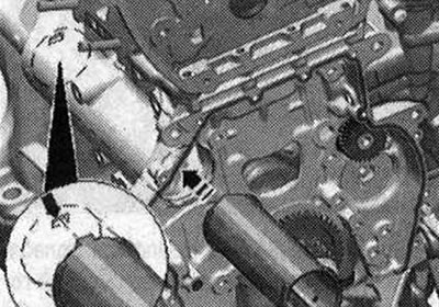
Turn the torsional vibration damper with the counter support "T10355" to the "TDC" position "arrow".
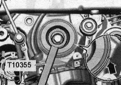
The notch on the torsional vibration damper must be located opposite the arrow mark on the lower cover of the chain drives. Unscrew the damper bolt using the support "T10355". Remove the torsional vibration damper. In order not to damage the gear engagement, screw in the damper bolt only with the mandrel "T10368".
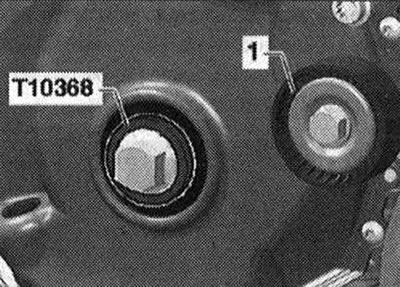
Screw the damper bolt and the mandrel "T10368" back in. Risk of engine damage. To avoid adjusting the timing phases, do not turn the crankshaft from the "TDC" position with the damper bolt removed. Remove the guide roller "1".
Unscrew the "arrow" bolts, remove the dipstick guide tube for determining the oil level from the drive chain cover. Unscrew the "1...15" bolts. Remove the lower chain drive cover.
Install
Monitor the expiration date of the silicone sealant. After applying the silicone sealant, install the cover within 5 minutes. Replace the bolts that were tightened with additional tightening. Replace all cuffs, gaskets and self-locking nuts. Remove the remains of the sealant on the cylinder block with a flat scraper. Check whether both dowel pins for centering the "arrow" cover are present.
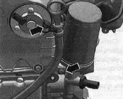
Cut off the tube spout at the front mark (hole diameter approx. 3 mm). Apply silicone sealant to the clean seating surface of the new cap as shown in the figure. Sealant strip thickness: 2...3 mm.
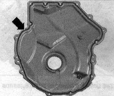
After applying the silicone sealant, install the cover within 5 minutes. The sealant bead should not be thicker than the specified width, otherwise excess sealant may get into the oil pan and clog the mesh filter in the oil intake pipe. After installing the cover, let the sealant dry for about 30 minutes. Only then can oil be added. Install the torsional vibration damper. Install the tensioner for the poly V-belt. Install the poly V-belt. Return to the service position. Install the front bumper trim and bumper. Install the front noise insulation screen. Check the oil level.
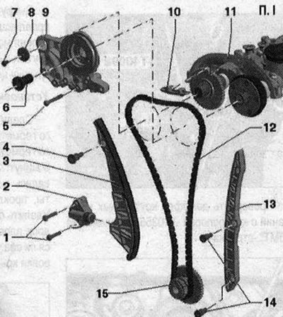
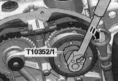
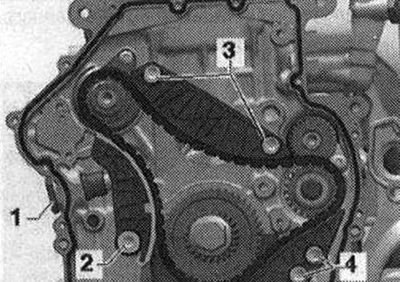
Camshaft chain drive I 1. Bolt 9 Nm; 2. The chain tensioner is under the action of a spring. Before removing, secure it with the insert pin "T40011"; 3. Tension bar for drive chain; 4. Guide bolt. 20 Nm; 5. Bolt. 9 Nm; 6. Distribution valve. Left-hand thread. 35 Nm. Remove with dismantling tool "T10352/1"; 7. Bolt. Replace. 20 Nm + 90°; 8. Washer; 9. Bearing bed; 10. Timing chain guide rail; 11. Camshaft housing; 12. Camshaft chain. Before removing, mark the direction of travel with paint; 13. Timing chain guide rail; 14. Guide bolt. 20 Nm; 15. Asterisk
Crankshaft Sprocket. Mounting Position
Both surfaces of the "arrow" must resist.
Removal the camshaft chain drive
Remove the front bumper trim and bumper. Bring to the service position. Remove the upper cover of the drive chain. The distribution valve has a left-hand thread. Remove the distribution valve using the "T10352/1" tool in the "direction of the arrow".
Unscrew the "arrow" bolts and remove the bearing bed.
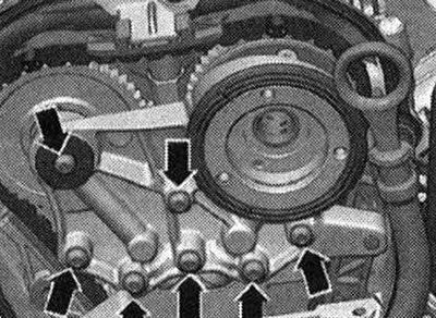
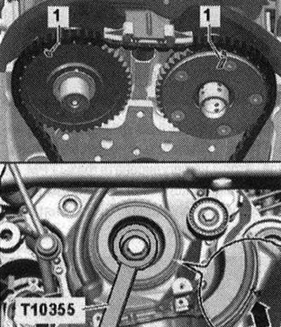
Turn the vibration damper with the counter support "T10355" to the "TDC" position "arrow". The notch on the vibration damper should be located opposite the arrow mark on the lower cover of the chain drives. The marks "1" of the camshafts should be facing upwards.
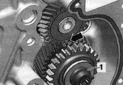
Remove the lower cover of the chain drive. Press the oil pump chain tensioner in the "direction of the arrow" and secure with the locking pin "T40011". Remove the oil pump chain tensioner "1". Remove the oil pump drive chain.
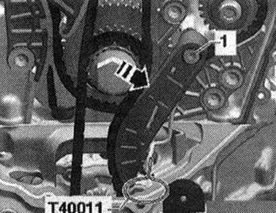
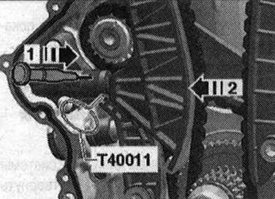
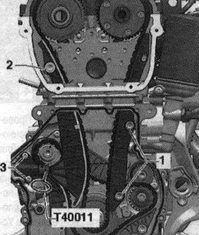
Raise the chain tensioner locking wedge by inserting a marking needle or a suitable screwdriver into the tensioner hole in the "direction of arrow 1". Press the drive chain tension bar in the "direction of arrow 2" and secure with pin "T40011".
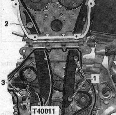
Remove the drive chain from the cylinder head. The intake camshaft switches to rotation in the direction of engine rotation. Remove the tension bar of the chain drive "2". Remove the camshaft chain drive damper bar "1". Remove the drive chain.
Install
The following tasks must be performed simultaneously. This requires the assistance of a second mechanic. The colored links of the camshaft timing chain must be installed according to the markings on the sprockets. Hold the wrench until the tensioner bar is installed. Fit the timing chain onto the exhaust camshaft. Fit the timing chain onto the crankshaft. Turn the intake camshaft with the wrench in the "direction of the arrow" and fit the camshaft chain
Install the camshaft chain tensioner bar and tighten bolt "2". Install the camshaft drive chain damper and tighten bolts "1". Fit the bearing housing and screw in the bolts "arrows" by hand. Remove the locking pin "T40011". Tighten the bolts "arrows" of the bearing housing. Install the distribution valve. Installation in the reverse order. In this case, it is necessary to consider the following: install the lower cover of the chain drive. Install the upper cover of the drive chain. Install the tensioner for the poly V-belt. Install the poly V-belt.
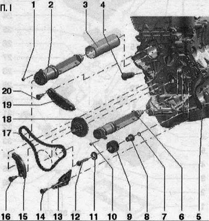
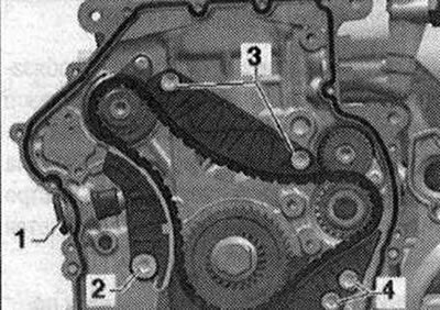
Balance shaft drive chain installation diagram 1. Bolt. Replace. 9 Nm; 2. Balance shaft. Must be replaced after removal. Lubricate the support with oil; 3. Balance shaft tube; 4. Chain tensioner. 65 Nm; 5. Cylinder block; 6. Balance shaft. Must be replaced after removal. Lubricate the support with oil; 7. Sealing ring. Lubricate with oil; 8. Support pin. Lubricate with oil; 9. Intermediate shaft gear for balance shaft. If the bolt has come loose, replace the intermediate shaft gear; 10. Bolt. Replace. 9 Nm; 11. Washer; 12. Bolt. If the bolt has come loose, replace the intermediate shaft gear; 13. Timing chain guide bar; 14. Guide bolt. 20 Nm; 15. Timing chain tensioner bar; 16. Guide bolt. 20 Nm; 17. Drive chain; 18. Asterisk; 19. Balance shaft drive chain guide rail; 20. Guide bolt. 20 Nm
Balance shaft tube. Mounting position
The balance shaft tube journal must be fixed in the "arrow" groove.
Support pin. Mounting position
Replace and lubricate the sealing ring "1". The mounting pin "arrow" of the support pin must enter the hole in the cylinder block. Lubricate the support pin.
Intermediate shaft gear. Tightening sequence
The intermediate shaft gear must be replaced. Otherwise, the gap on the tooth profile is not created - engine damage! The new intermediate shaft gear has a varnish coating that quickly wears off and thus the machine creates a gap in the tooth profile.
Tighten the new bolt in the following order
- 1. Pre-tighten with a torque wrench to 10 Nm.
- 2. Rotate the intermediate shaft gear. The intermediate shaft gear should not have any clearance, otherwise loosen and tighten again
- 3. Tighten with a torque wrench to 25 Nm.
- 4. Tighten 90° with a regular wrench.
Removal the balance shaft chain drive
Remove the upper cover of the drive chain. Remove the lower cover of the chain drive. Remove the camshaft chain drive. Remove the camshaft chain drive damper bar "1". Remove the camshaft chain drive tensioner "3".
Remove balance shaft drive chain tensioner "1". Remove tension bar "2". Remove damper "3". Remove damper "4". Remove drive chain.
Install
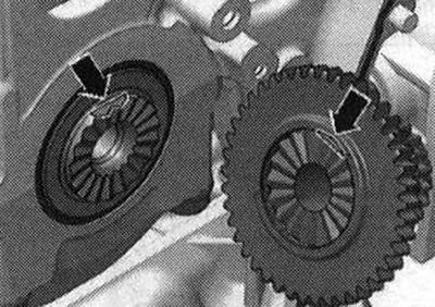
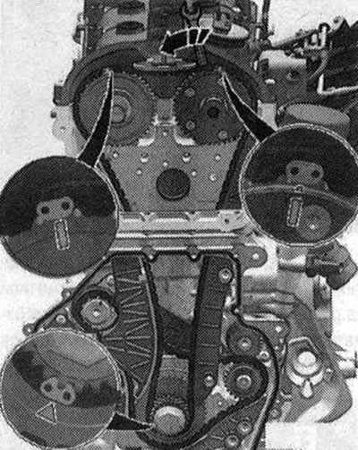
Turn the intermediate shaft sprocket/balance shaft to the "arrow" markings. The colored links of the timing chain must be installed according to the markings on the sprockets. Put on the timing chain, the colored links of the timing chain must be installed according to the markings on the sprockets.
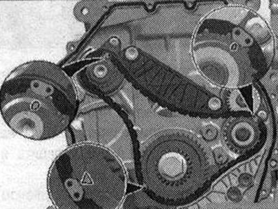
Install the drive chain tensioner and tighten the bolts "4". Install the drive chain tensioner and tighten the bolts "3". Install the drive chain tensioner bar and tighten the bolt "2". Install the chain tensioner "1" using thread varnish.
Check the adjustment again. Check the markings on the intermediate shaft/balance shaft sprocket "arrows". For clarity, the markings on the intermediate shaft/balance shaft are shown with the chain removed. Install in the reverse order. In this case, note the following: Install the camshaft chain. Install the lower cover of the chain drive. Install the upper cover of the drive chain. Install the tensioner for the poly V-belt. Install the poly V-belt.
Checking the timing phases
Remove the upper chain drive cover. Remove the sound insulation. Turn the vibration damper from below, in the direction of engine rotation, to the position
"TDC" "arrow".
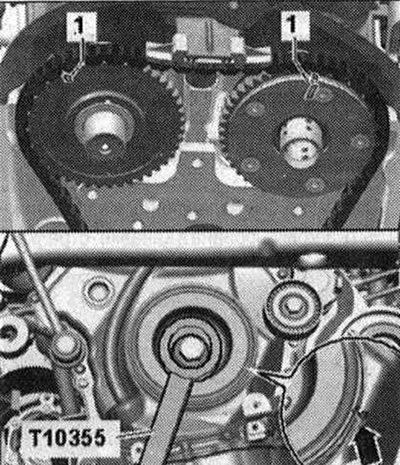
To turn the vibration damper, use a ratchet with a SW 24 replaceable head. Set the vibration damper in the direction of engine rotation to "TDC". Do not adjust the TDC position by turning it in the opposite direction! The notch on the vibration damper must be located opposite the arrow mark on the lower cover of the chain drives (use a mirror). The "1" marks on the camshafts must face upwards.
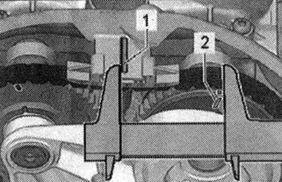
Measure the distance from the outer edge of the jumper "1" to the mark "2" on the intake camshaft. Mandatory value: 61...64 mm.
When the required value is reached, measure the distance between the mark on the intake camshaft "3" and the mark on the exhaust camshaft "4". Required value: 124...126 mm.
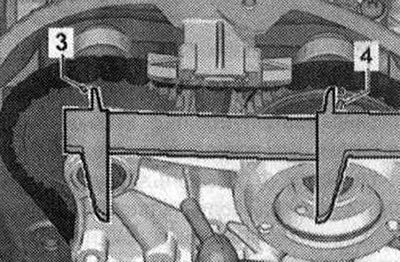
An offset of 1 tooth results in a deviation of approximately 6 mm from the required value. If an offset is detected, the drive chain must be re-applied.