



Note. The engine is removed upwards without the gearbox. For disposal or reuse, the coolant should be drained into a clean container. When reassembling, install all binders in the places where they were originally installed. Risk of damage to electronic components when disconnecting battery terminals. Follow the instructions when disconnecting battery terminals.
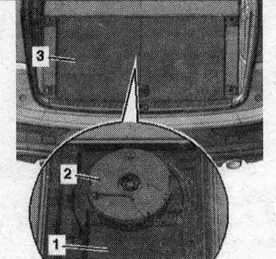
Turn off ignition. Remove trunk bottom "3". Remove Bassbox "2" if present. Unscrew floor covering "1" above cover.
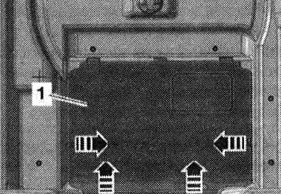
Unlock the "arrow" fasteners and install cover "1".
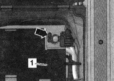
Open cover "1" above the (-) battery pole. Disconnect the ground wire "arrow" from the battery terminal.
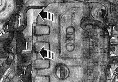
Remove the engine cover "arrows"
Caution. Risk of burns from hot steam and hot coolant. When the engine is warm, the cooling system is under excess pressure. To relieve excess pressure, place a rag around the coolant expansion tank cap and carefully open it.
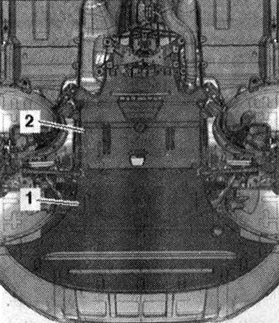
Open the expansion tank cap. Remove the front wheels: right and left. Remove the front right and left mudguard. Remove noise insulation screens "1" and "2".
Caution! Risk of damage to the previously used poly V-belt when changing its running direction. For reinstallation, mark the running direction of the poly V-belt with chalk or a felt-tip pen before removing it.
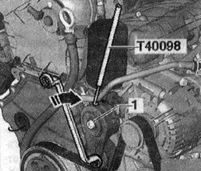
To loosen the poly V-belt, turn the tensioner "in the direction of the arrow". Secure the tensioner with the "T40098" lock. Remove the poly V-belt. Unscrew bolt "1" and remove the poly V-belt tensioner from the auxiliary unit bracket.
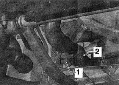
Install the tray for the service taps "VAS 6208" under the engine. Screw the drain tap "1" onto the nipple and drain the coolant, then remove the nipple "2" from the radiator, to do this, lift the clamp bracket.
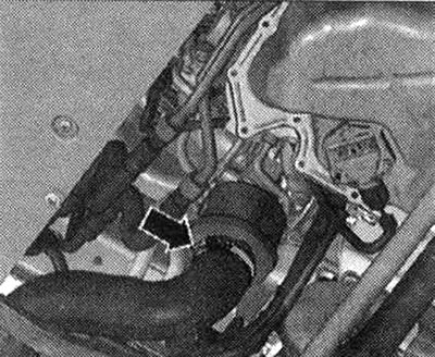
Disconnect the hose clamp "arrow", remove the air duct hose and set it aside.
Loosen the "arrow" nut on the right side member and release the ground cables.
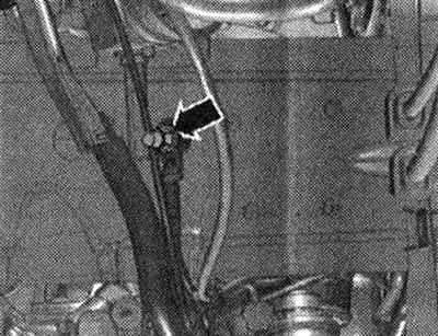
Caution! Risk of damage to the front muffler release components. Do not tilt the front muffler release components more than 10°.
Unscrew the threaded connections "arrows", move the clamping sleeve back.
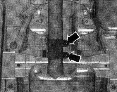
Lower the front muffler a little and tie it to the crossbar "arrow".
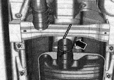
Disconnect the "arrow" connector from the steering gear.
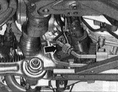
Cars with DSG gearbox: Risk of gearbox control unit failure (Mechatronik) due to static discharge. Do not touch the plug contacts of the CP plug with your hands. Disconnect the connector from the CP by turning the rotary lock counterclockwise "arrow".
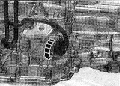
Release the wiring harness. Unscrew the bolts securing the ATF line "arrow".
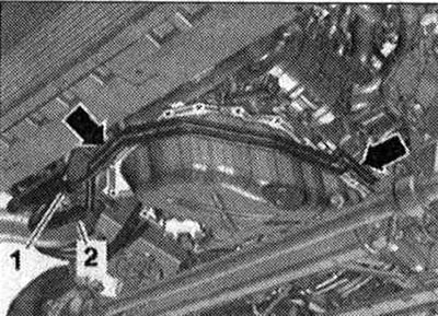
"Pos. 1, 2" do not take into account. Place a rag under the disconnection point to collect the leaking transmission oil. Unscrew the bolt "arrow", disconnect the ATF lines from the gearbox and put them aside.
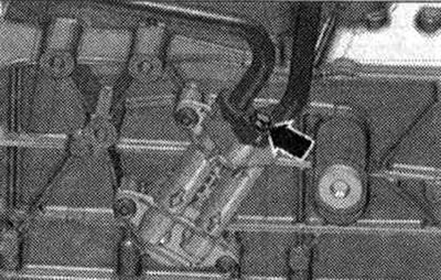
To prevent contamination from entering, close the disconnected lines and pipes on the intercooler with a clean plug from the plug kit for the VAS 6122 engine.
All
Remove cover "1" from the bottom of the "arrow" gearbox.
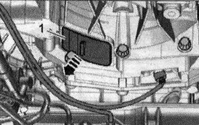
Unscrew the 3 bolts "arrow" of the driven disk, to do this, turn the crankshaft accordingly through 120° in the direction of engine rotation.
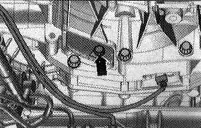
Cars with manual transmission: Unscrew bolts -1,6,7,8,9,10,11- connecting the engine to the transmission. Ignore "Pos. A".
Cars with DSG gearbox: Unscrew the bolts "1,6,7,8,9,10" engine connection to gearbox. "Pos. A" should not be taken into account.
All
Disconnect the plug connector "1" of the electromagnetic clutch from the air conditioning compressor.
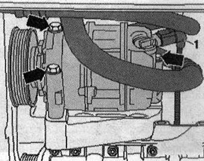
Warning: Risk of injury due to refrigerant leakage. Do not open the air conditioning circuit of the air conditioning system.
Remove the air conditioning compressor "arrow" bolts.
Caution! Risk of damage to the hoses and lines of the cooling system. Do not overtighten, bend or fold the refrigerant lines and hoses.
Tie the compressor with the coolant hoses connected to the side member from above. Remove the electrical connector "1" of the radiator fan from the bracket, to do this, move the lock back "arrow" and press the stopper down.
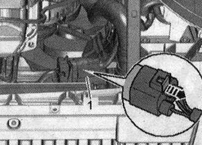
Release the electrical cables to the radiator fan control unit. Remove the coolant hoses by loosening the fastening clamps "1" and "3". Ignore "Pos. 2" and "arrows".
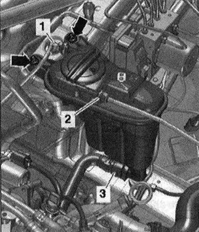
Loosen the clamps for the "arrow" hose and remove the air duct hose.
Disconnect the plug connector of the boost pressure sensor "G31" "pos. 1" and release the connector.
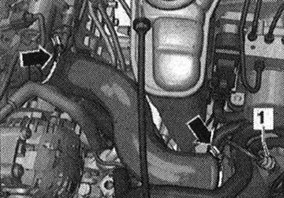
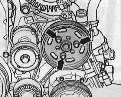
Unscrew the "arrow" bolts, for this use the 2-hole "3212" key as a support, remove the poly-V belt pulley of the impeller pump.
Unscrew bolts "1" and "3". Ignore "Pos. 2".
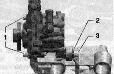
Place the common hydraulic booster pump with the connected hydraulic lines on the side member. Remove the coolant hose by loosening the fastening bracket "2". Do not take "Pos. 1" into account.
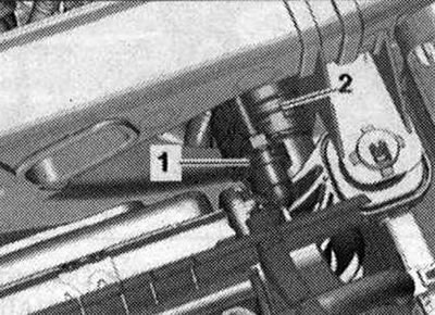
Unscrew bolts "1" and "2" and place the coolant pipe with the connected coolant hoses "arrows" on top.
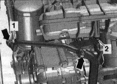
Disconnect connectors "1 and 4" from the oil pressure sensor "F22" and the low pressure oil pressure sensor "F378".
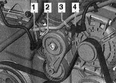
Remove the air duct "arrow".
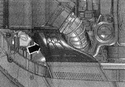
Disconnect plug connector "2" of air flow meter "G70". Remove air duct hose from air flow meter "G70" by loosening clamp "3". Remove air filter housing "1" upwards.
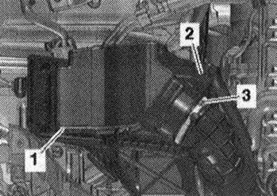
Caution! Risk of contamination of the fuel system. When working on the injection system, observe the rules for maintaining cleanliness.
Disconnect the fuel supply hose "1" by pressing the locking ring. Disconnect the hose "2" from the activated carbon absorber.
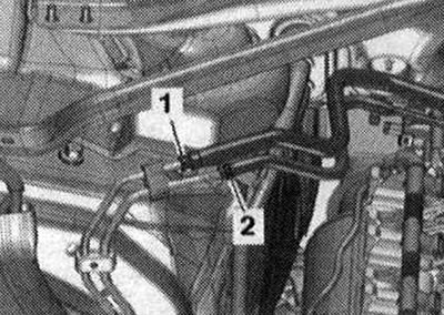
Unscrew bolts "1", as well as nuts "2" and "3", remove the tensioner.
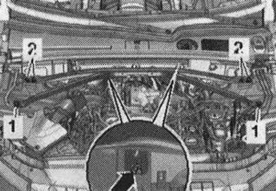
Remove the foam elements "1" and "2" from the left and right in an upward direction.
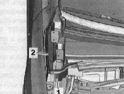
Remove seal "3". Release fastening clamps "1" from fasteners and remove water drainage box cover "2".
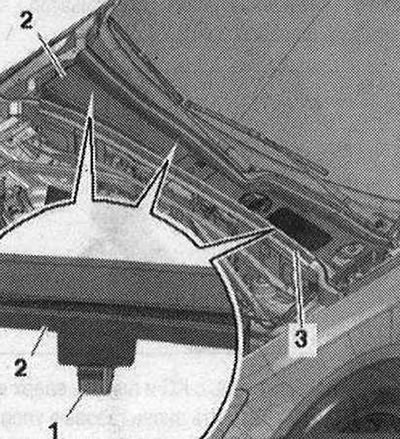
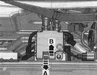
Unlock the lock "arrow A" and open the cover "arrow B".
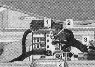
Unscrew nuts "1" and "2" of the electrical wiring. Remove connector "3" from the bracket and disconnect it. Unscrew bolt "4" and remove branch pipe 2 cl. 30 "TV22" from the front wall of the water drainage box "arrow".
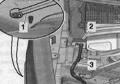
Unlock the wheel arch latches with a 5.5 union wrench "pos. 1" and remove the cable gland "2" in the upward direction. Release the wiring harness "3" going to the alternator and starter with the "80-200" release lever
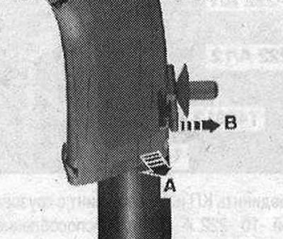
Release the cable channel by unlocking the lock "arrow B" and pulling the cable channel upwards "arrow A".
Remove the vacuum pipe "1" from the end wall of the water drain box; to do this, disconnect the vacuum hose "23" on the back side of the "arrow".
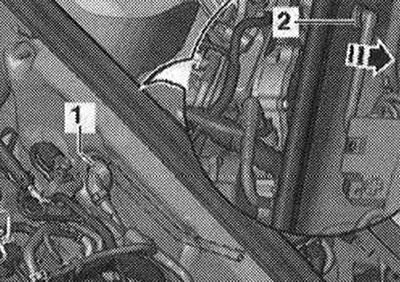
Unscrew bolt "2" and nut "3". Remove filler neck "1" with filler tube from washer reservoir, passing it through body opening "arrow".
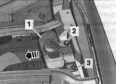
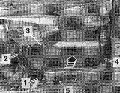
Remove the clamps "arrow A" and open the cover "arrow B" of the engine control unit.
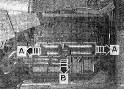
If present, disconnect electrical connector "2". Disconnect plug connectors "4" and unscrew electrical wiring "3". Unlock the "arrow" latches and remove fuse block B "SB" "pos. 1". Remove and release the engine wiring harness secured in the switching block.
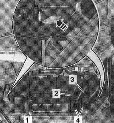
Unlock the clamps "arrow A" and remove the cable guide "2" in the upward direction "arrow B". Release the wiring harness, place it on the engine and secure the engine control unit from falling. Ignore "Pos. 1".
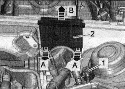
Mark coolant hoses "1" and "2" for reassembly and remove by pressing the fastening brackets. Press the coolant hoses into the water drain box with the hose inlet.
Ignore the "arrow". Disconnect the plug connectors and release the electrical wires:
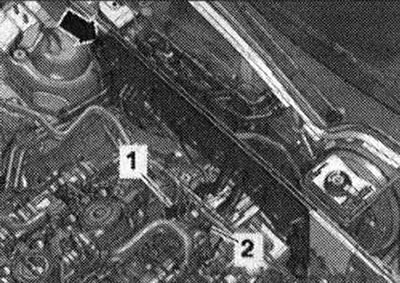
1. For lambda probe "G39"
2. Lambda probe after the catalytic converter "G130"
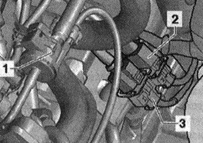
Unscrew the "arrow" nuts and press the catalytic converter back.
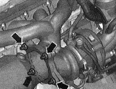
Cars with manual transmission: Unscrew bolts "2...5" connecting the engine to the transmission. Ignore "Pos. A".
Cars with DSG gearbox: Unscrew bolts "2...5" connecting the engine to the gearbox. Ignore "Pos. A".
All
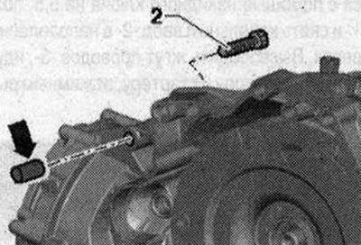
Remove the starter from the gearbox and leave it in the mounting position. Bolt "2" secures the starter to the gearbox and has an additional spacer sleeve "arrow".
Attach the "T40013" suspension to the gearbox and close the fuse. Install the "10-222 A" crossmember on the shock absorber cups on the left and right, as shown in the figure.
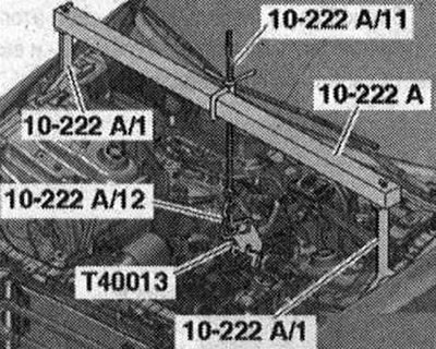
Connect the gearbox and lead screw with the "10-222 A/12" load bracket and the "T40013" suspension device. For better representation, the installation position is shown with the engine removed. Suspend the "2024 A" suspension device by the engine lugs and by the "VAS 6100" crane using the "VAS 6101" lifting lever/crane extension, as shown in the figure.
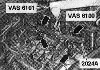
To align the center of gravity of the power unit, the hook bars must be inserted as shown in the figure.
Unscrew the left and right bolts "1" of the engine mount. Unscrew the nut "2" and remove the wiring bracket.
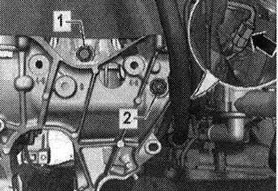
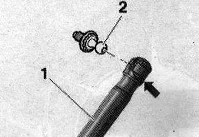
Ignore the "arrow". Raise the engine enough to release the engine mounts. Tighten the lead screw of the support-console "10-222 A". Risk of damage to the hose and wire connections, as well as the engine compartment. Make sure that all hose and wire connections between the engine, gearbox, subframe and body are disconnected. When removing the engine, carefully remove it from the engine compartment. When removing the engine, the second mechanic must carefully open the hood, ensuring the maximum opening angle. To do this, slightly pry the locking spring "arrow" with a small screwdriver and remove the gas-filled shock absorber "1" from the top of the ball joints "2".
Remove the engine from the gearbox and lift it upwards from the engine compartment. Reinstall the gas struts onto the ball joints.
[Material republished from the website: AUDImanual]