



Table of contents: Tightening torques (Nm) ↓ Engine to manual transmission ↓ Engine to DSG gearbox ↓ All ↓ All ↓ Support of units ↓
Tightening torques (Nm)
Note. The tightening torques given are valid for lightly greased, phosphated or oxidised nuts and bolts. The use of additional lubricants, such as motor or transmission oils, is permitted, except for graphite-containing ones. Do not use degreased parts. The tightening torque tolerance is +15%.
| Bolts and nuts M6 | 9 |
| M7 | 15 |
| M3 | 20 |
| M10 | 40 |
| M12 | 65 |
| Nut for ground wire | 9 |
Engine to manual transmission
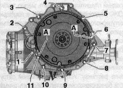
| Pos. | Bolt | N·m |
| 11) | M10x502) | 65 |
| 23), 7 | M12x1004) | 30 + 90° |
| 3 5), 6 | M12x754) | 30 + 90° |
| 4,5 5) | M12X120 4) | 30 + 90° |
| 8,9,10 | M10x754) | 15 + 90° |
| 11 | M 12x504) | 30 + 90° |
| A | Centering bushings | Centering bushings |
Engine to DSG gearbox
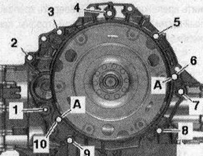
| Pos. | Bolt | Nm |
| 11) | M10x502) | 65 |
| 23),7 | M12X100 4) | 30 + 90° |
| 35),6 | M 12x754) | 30 + 90° |
| 4,55) | M12x1204) | 30 + 90° |
| 8,9 | M10x75 4) | 15 + 90° |
| 10 | M 12x504) | 30 + 90° |
| A | Centering bushings | Centering bushings |
- 1) Additionally secures the starter
- 2) The bolt strength class is 10.9, the steel bolt can be used repeatedly.
- 3) Additionally secures the starter; with an additional spacer sleeve between the starter and gearbox.
- 4) Use bolts twice.
- 5) Additionally secures the wiring bracket.
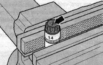
Aluminum bolts can be used twice. Therefore, after the first use, mark such bolts with two notches "X" "arrow" with a cutter. In order not to damage the bolts when notching, do not fasten them in a vice. Insert the bolt as shown in the figure into the 14 socket head with a 1/2-drive, which can then be fastened in a vice. Do not reuse bolts marked with "X".
Note. Replace bolts that were tightened with additional tightening. Replace self-locking nuts, lip seals, gaskets and O-rings. On vehicles with a manual transmission, a needle bearing must be installed in the driven disk. Before installing the disk, make sure that the needle bearing is already installed. Pressing the needle bearing into the driven disk. Hose nipples, air duct tubes and hoses must be cleaned of oil and grease before installation. Use clamps of the appropriate series to secure all hose connections. To ensure reliable fastening of the air duct hoses to the nipples, treat the threaded connections of the already used clamps with a rust remover. During installation, all cable ties must be placed in their original places.
It is imperative to clean the threaded holes for fixing the power unit in the cylinder block before assembling the gearbox with a tap. Before connecting the engine and gearbox, perform the following preparatory actions: install the mounting device "T40169" from below under the gearbox housing and dual-mass flywheel, as shown in the figure. The mounting device must fit into the semicircular groove "1" and additionally into the control hole "2".
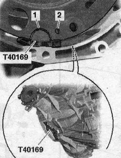
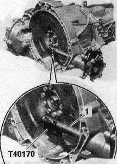
In order to find the inspection hole, it is necessary to turn the dual mass flywheel. Insert the mounting device bolts into the hole on the gearbox housing. Install the "T40170" transportation protection from below under the gearbox housing and attach it to the shaft with flange "1".
Bolt "2" secures the starter to the gearbox and additionally has a spacer sleeve "arrow". The spacer sleeve should be located between the starter and the gearbox. If necessary, check the possibility of reusing the aluminum engine mounting bolts on the gearbox and mark them.
Cars with manual transmission: Check the presence of centering bushings "A" of the engine and transmission in the cylinder block, insert the bushings if necessary. Install the transmission on the engine and tighten bolts "2...5".
Cars with DSG gearbox: Make sure that there are mounting bushings "A" for aligning the engine and gearbox in the cylinder block; if necessary, insert the missing bushings. Install the gearbox on the engine and tighten bolts "2...5".
All
Unload the spindle "10-222 A/11". Lower the crane and place the engine with the gearbox on the engine mounts. Install the engine mount. Remove the service crane "VAS 6100" and the hanging device "2024 A". Tighten the remaining connecting bolts of the engine on the gearbox. Remove the transport fastener "T40170" and the mounting device "T40169".
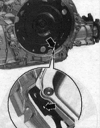
Cars with manual transmission: The following step is necessary to ensure that the clutch module fits evenly on the driven disk and does not warp. Install the front wheels. Engage 4th gear and rotate the front wheels in the direction of travel until the clutch module makes a full revolution. The inspection hole "arrow" should again be visible in the recess of the gearbox housing.
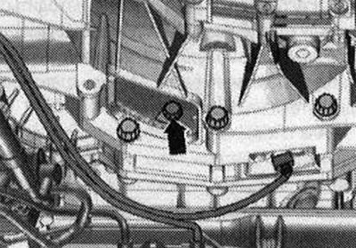
Secure the clutch module to the driven disk as follows: screw in the first bolt "arrow" by hand (2 Nm).
Turn the front wheels in the direction of travel until the clutch module rotates 240°. Tighten the accessible bolt in this position to the specified torque. Turn the front wheels in the direction of travel until the clutch module rotates 120°, and tighten the remaining 2 bolts to the tightening torque.
Cars with DSG gearbox: The following step is necessary to ensure that the clutch module fits evenly on the driven disc and does not warp. Lightly press the clutch module "2" with the mounting lever "1" onto the driven disc "3" "in the direction of the arrow".
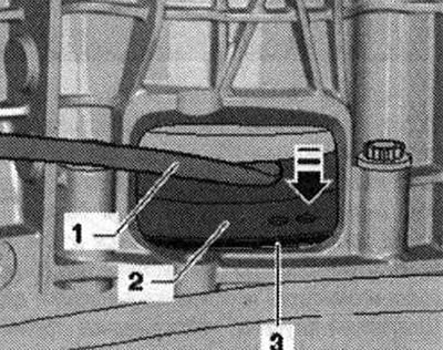
Secure the clutch module to the driven disk as follows: screw in the first bolt "arrow" by hand (2 Nm). Next, turn the crankshaft by the flywheel using the counter support "T10355" by 240° in the direction of engine rotation.
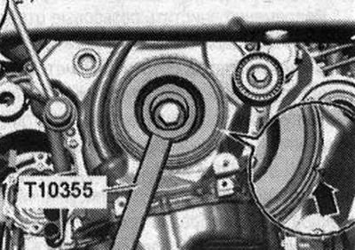
In this position of the crankshaft, tighten the accessible bolt to the specified torque. Turn the crankshaft 120° and tighten the remaining 2 bolts to the specified tightening torque. Ignore the "arrow".
All
Install the catalytic converter. Install the front muffler. Install the small coolant pipe. Connect the coolant hoses using a union nut. Install the vane pump. Install the compressor. Electrical connections and wiring. Install the engine control unit. Install the wires, the 2-terminal 30 "TV22" splitter and the cover of the engine compartment switching unit. Install the tensioner. Install the windshield washer reservoir filler pipe. Pay attention to the work on installing the battery. Risk of damage to the control units due to overvoltage. Do not use a charger to start the engine! Install the air filter housing. Check the oil level. Fill with coolant. Install the mudguards and sound insulation. Install the front wheels.
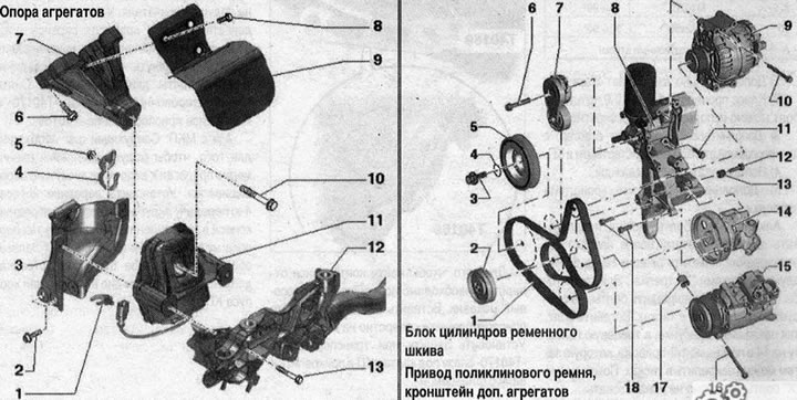
Support of units
- 1. Not installed
- 2. Bolt 20 Nm
- 3. Gearbox retainer for engine mount. If the engine mount is defective, replace the mounting plate. Check the mounting plate on the opposite side, replace if necessary
- 4. Bracket for hydraulic line
- 5. Nut. 9 Nm
- 6. Bolt. 40 Nm
- 7. Engine support
- 8. Bolt. 10 Nm
- 9. Thermal insulation
- 10. Bolt. Replace. 90 Nm + 90°
- 11. Engine support with solenoid valve of left electrohydraulic engine support "N144" (only on the left). Replace only in pairs
- 12. Subframe
- 13. Bolt. 55 Nm
Material republished from the website AUDImanual.ru