
Table of contents: Crankcase ventilation. Tightening… ↓ Disconnecting the cylinder head ↓ Cylinder head bolt tightening… ↓ Removal the cylinder head ↓ Install ↓
Note. Replace the cylinder head mounting bolts. When performing installation work, replace the self-locking nuts, bolts that are tightened with additional tightening, as well as the sealing rings and gaskets. The plastic linings included in the repair kit for protecting open valves may be removed immediately before installing the cylinder head. If the cylinder head or cylinder head gasket has been replaced, the coolant and oil must be replaced.
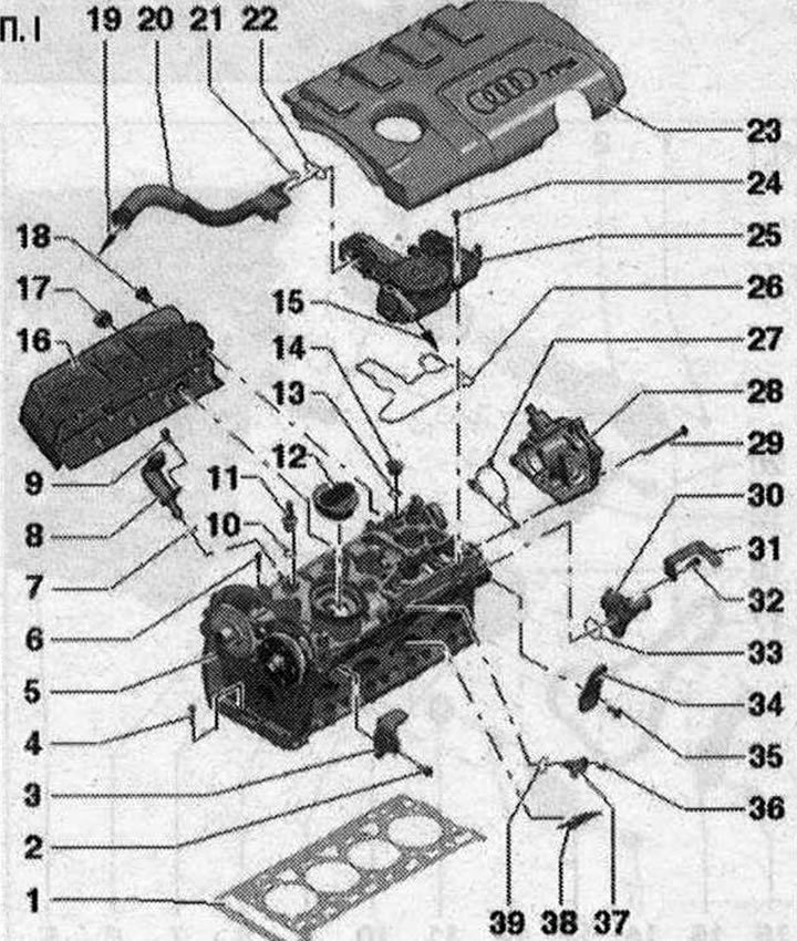
I 1. Cylinder head gasket. Replace. Observe the installation position: part number for the cylinder head; 2. Bolt 25 Nm; 3. Cargo eye; 4. Bolt. Replace. Observe the sequence of actions when unscrewing. Observe the sequence of actions when tightening; 5. Cylinder head. Check the plane curvature; adjacencies; 6. Cylinder head bolt. Replace. Observe the sequence of actions when unscrewing. Observe the sequence of actions when tightening; 7. Sealing ring. Replace. Lubricate with oil; 8. Phase shifter actuator; 9. Bolt. 5 Nm; 10. Sealing ring. Replace. Lubricate with oil; 11. Plug. 5 Nm. With ball head for engine casing; 12. Lid with seal; 13. Sealing ring. Replace. Lubricate with oil; 14. Plug; 15. To the intake manifold; 16. Thermal insulation shield; 17/18. Bolt. 20 Nm; 19. To intake manifold/turbocharger; 20. Ventilation pipe; 21. Sealing ring. Not a spare part; 22. Gasket. Not a spare part; 23. Engine casing; 24. Bolt; 25. Engine crankcase ventilation; 26. Gasket. Not a spare part; 27. Gasket. Replace if damaged; 28. Vacuum pump; 29. Bolt; 30. Connecting pipe; 31. Mounting shield; 32. Bolt. 9 Nm; 33. Sealing ring. Replace. Moisten with coolant; 34. Cargo eye; 35. Bolt. 25 Nm; 36. Bolt. 9 Nm; 37. Hall sensor "G40"; 38. Partition; 39. Sealing ring. Replace. Lubricate with oil
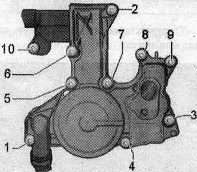
Crankcase ventilation. Tightening sequence
Note. Self-tapping bolts. When replacing the cylinder head, use only original bolts, as the cylinder head is supplied without threads for fastening the engine crankcase ventilation mechanism. Tapping the threads is not allowed.
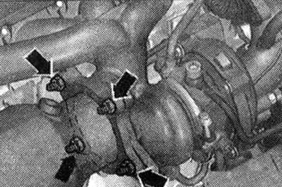
Tighten the engine crankcase ventilation system bolts in the sequence "1...10" to a torque of 11 N·m.
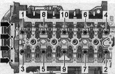
Disconnecting the cylinder head
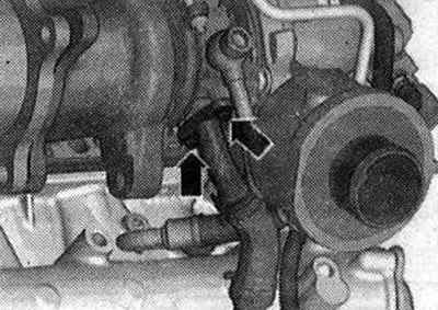
Unscrew the bolts "arrows". Loosen the cylinder head bolts in the sequence "1...10".
Cylinder head bolt tightening sequence
Tighten the cylinder head bolts in the sequence "1...10" as follows.
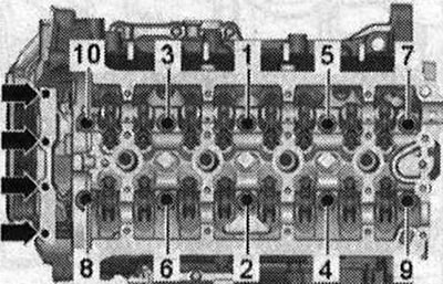
- 1. Pre-tighten with a torque wrench to 40 Nm.
- 2. Tighten 90° with a regular wrench.
- 3. Tighten 90° with a regular wrench.
- 4. Pre-tighten the arrow bolts to 8 Nm.
- 5. Tighten the arrow bolts with a hard wrench by 90°.
Removal the cylinder head
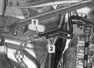
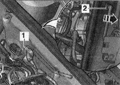
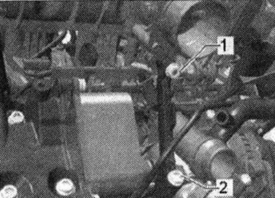
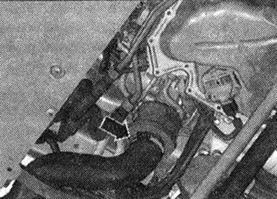
When reassembling, install all binders in the places where they were originally installed. Tightly close the open channels of the intake circuit and the exhaust system with the appropriate plugs. For example, from the plug set for the engine "VAS 6122". Remove the camshafts. Risk of damage to the valves and piston crowns. Once the camshafts are removed, the crankshaft can no longer be turned. Remove the front sound insulation. Drain the coolant. Remove the front muffler. Remove the rear coolant hoses to the cylinder head. Disconnect the fuel supply hose "1" by pressing on the locking ring. Disconnect hose "2" from the activated charcoal absorber.
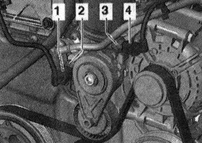
Unscrew bolts "1", as well as nuts "2" and "3", remove the tensioner.
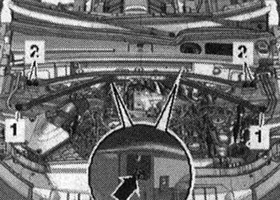
Remove the foam elements "1" and "2" from the left and right in an upward direction.
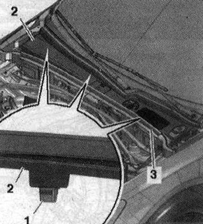
Remove the gasket "3". Release the fastening clamps "1" from the fasteners and remove the cover of the water drainage box "2".
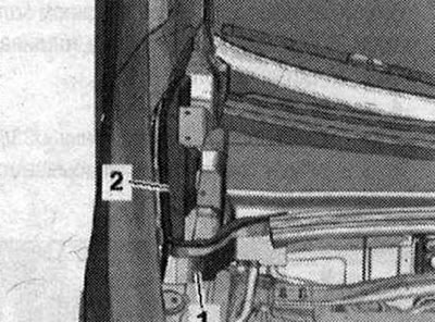
Remove the vacuum pipe "1" from the end wall of the water drainage box, for this disconnect the vacuum hose "2" on the rear side "arrow". Remove the front bumper trim and bumper. Bring to the service position.
Loosen the clamps for the "arrow" hose and remove the air duct hose.
Disconnect the following connectors:
2. Remove from knock sensor 1 "G61" and release
3. from the intake manifold flap valve "N316", fuel pressure sensor.
G247- and Hall sensor "G40"
4. from injectors
5. from the throttle valve block "J338"
6. from the intake air temperature sensor "G42"
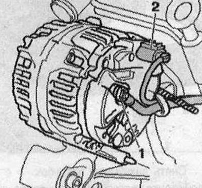
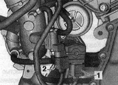
Disconnect connector "2" and release the wire.
Unscrew the coolant line bracket "arrow".
For better understanding, the installation position is shown with the engine removed. Remove the intake pipe branch pipe by unscrewing the fastening nut "1" and bolt "2".
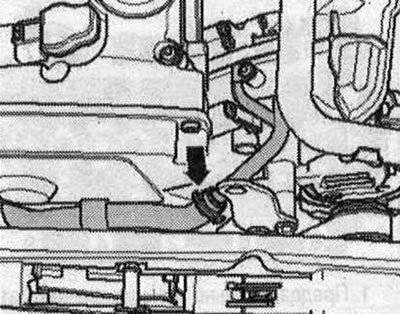
Disconnect the cooling system hose "arrow".
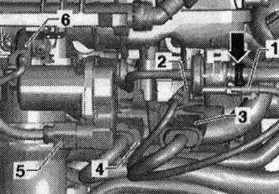
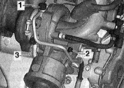
Unscrew bolts "1 and 2" and set aside the oil supply line. Unscrew bolt "3" and set aside the coolant line.
Disconnect the hose clamp "arrow", remove the air duct hose and set it aside.
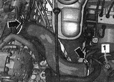
Disconnect connectors "1 and 4" from the oil pressure sensor "F22" and the low pressure oil pressure sensor "F378".
Disconnect connectors "1 and 2" and release the electrical wiring.
Unscrew the "arrow" bolts and remove the turbocharger support.
Unscrew the bolts "arrow" of the oil drain pipe.
Unscrew the "arrow" nuts and move the catalytic converter back.
Unscrew the bolts "arrows". Unscrew the cylinder head bolts in the sequence "1...10". Check whether all wires and cables are released! Watch the tension bar and the chain guide bar when lifting the cylinder head. Remove the cylinder head. Place the cylinder head on a soft lining (foam).
Install
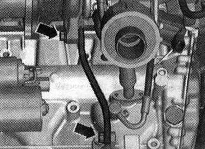
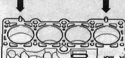
Risk of damage to the sealing surface. Carefully remove any remaining sealant from the cylinder head and cylinder block. Avoid the formation of long scratches or scoring. Risk of damage to the cylinder block. There must be no oil or coolant in the blind holes of the cylinder head fastening bolts. Risk of a leaky cylinder head gasket. Carefully remove any remaining emery and sanding material. Remove the new cylinder head gasket from the packaging immediately before installation. Handle the gasket with particular care to prevent damage to the silicone layer and the grooves of the cylinder head gasket. Risk of damage to open valves. When installing an exchange cylinder head, remove the plastic base to protect the open valves only if it comes into direct contact with the cylinder head. Risk of damage to the valves and piston crowns after working on the valve mechanism. Carefully turn the engine at least 2 turns to ensure that none of the valves come into contact with the cylinder head during operation. Replace any bolts that were tightened further. Replace all seals, gaskets and self-locking nuts. Pay attention to different sealants for the cylinder head mounting surfaces and bolts. Before installing the exchange cylinder head, it is necessary to lubricate the mating surfaces of the hydraulic compensators, rocker arms and the working surface of the cams with oil. Hose nipples and air duct tubes and hoses of the system must be cleaned of oils and grease before installation. Use clamps of the appropriate series to secure all hose connections. To ensure reliable fastening of the air boost hoses on the nipples, treat the threaded connections of the already used clamps with a rust remover. If the cylinder head or cylinder head gasket was replaced, it is necessary to replace the coolant and oil. Install the cylinder head seal. Take into account the centering pins in the cylinder block "arrows".
(This publication is borrowed from the resource: AUDIMANUAL.RU)