



Table of contents: Cooling system hose connection… ↓ Draining and filling coolant ↓ Bay ↓ Ratio of components in coolant ↓ Installation diagram of the coolant… ↓ Coolant pump and thermostat ↓ Coolant pump mounting bolt… ↓ Removal the coolant temperature… ↓ Insertable design ↓ Screw-on design ↓ Install ↓ Removal the toothed belt of the… ↓ Install ↓ Removal the water pump ↓ Install ↓ Removal the thermostat ↓ Install ↓ Radiator, rim and radiator fan… ↓ Connecting the coolant hose with… ↓ Removal the radiator together with… ↓ Install ↓ Removal the fan frame ↓ Install ↓
Caution. Risk of burns from hot steam and hot coolant. When the engine is warm, the cooling system is under excess pressure. To relieve excess pressure, first cover the expansion tank cap with a rag and carefully open it. When the engine is warm, the cooling system is under pressure. If necessary, release the pressure before performing repair work. Use clamps of the appropriate series to secure all hose connections. It is recommended to use hose clamp pliers to install spring clamps
- "V.A.G 1921" or hose clamp pliers
- VAS 6340-. Gaskets and sealing rings must be replaced. The arrows on the ends of the pipes and hoses of the cooling system must be opposite each other.
Cooling system hose connection diagram
Cars without independent heater
Blue = Large coolant circuit. Red = Small cooling circuit. Brown = Heating circuit.
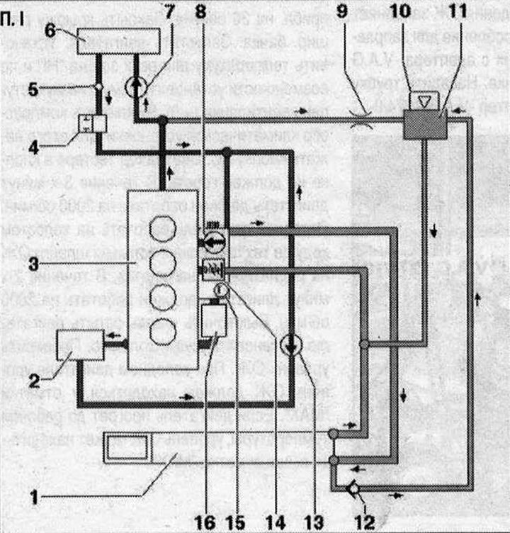
I 1. Radiator. After replacement, change the coolant; 2. To the turbocharger; 3. Cylinder head/cylinder block. After replacement, change the coolant; 4. Coolant supply shut-off valve. Controlled via the reduced pressure Climatronic coolant shut-off valve "N422"; 5. Ventilation hole; 6. Heater heat exchanger. After replacement, change the coolant; 7. Coolant circulation pump "V50". Installed only in cars with engine start and stop system; 8. Water pump; 9. Throttle; 10. Coolant expansion tank cap; 11. Expansion tank; 12. Check valve;13. Coolant pump after engine shutdown "V51" (installed only on vehicles designed for hot countries; 14. Thermostat; 15. Coolant temperature sensor "G62"; 16. Engine oil cooler
Car with independent heater
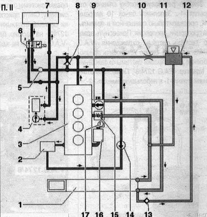
II 1. Radiator. After replacement, change the coolant; 2. To the turbocharger; 3. Cylinder head/cylinder block. After replacement, change the coolant; 4. Autonomous heater; 5. Ventilation hole; 6. Heater coolant shut-off valve "N₂79"; 7. Heater heat exchanger. After replacement, change the coolant; 8. Check valve. The arrow shows the direction of flow; 9. Water pump; 10. Throttle; 11. Coolant expansion tank cap; 12. Expansion tank; 13. Check valve; 14. Coolant bleed pump after engine shutdown "V51" (installed only on vehicles designed for hot countries); 15. Thermostat; 16. Engine oil cooler; 17. Coolant temperature sensor "G62"
Draining and filling coolant
Open the expansion tank cap. Remove the front noise insulation "1". Install the tray for service cranes "VAS 6208" under the engine. Unscrew the threaded plug of the drain hole "1" and drain the coolant.
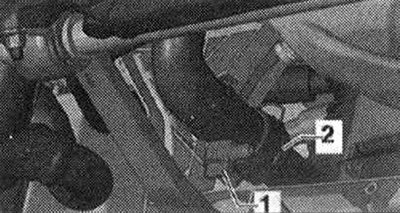
"Pos. 2" should not be taken into account.
Bay
Note. The cooling system is filled with a coolant solution and coolant additives for the entire year. Only use the coolant according to the electronic spare parts catalog. Other concentrates may impair the properties of the coolant, especially the anti-corrosion properties. The resulting damage may cause leaks in the cooling system and lead to serious engine malfunctions. Coolants with the correct ratio of mixture components prevent the formation of corrosion and limescale. In addition, they increase the boiling point. Therefore, a concentrate must be present in the cooling system throughout the year. Especially in countries with a tropical climate, with high engine loads, a coolant with a higher boiling point reliably protects the engine during operation. The freezing point of the coolant must be at least -25°C (in countries with an arctic climate, at least -35°C). It is also prohibited to reduce the proportion of concentrate in the coolant in the warm season or when operating in countries with a warm climate by adding water to the cooling system. The proportion of concentrate must be at least 40%. If the freezing point of the coolant needs to be reduced due to climatic conditions, the additive content can be increased, but not more than to 60% (the freezing point in this case will be about -40°C). If this limit is exceeded, the freezing point of the coolant will increase again, and, in addition, the efficiency of the cooling system will decrease. Use only clean drinking water to mix the coolant. When replacing the radiator, heater heat exchanger, cylinder head, cylinder head gasket or cylinder block, reusing the drained coolant is prohibited. Contaminated coolant must not be used again. A refractometer "TW007" should be used to check the concentrate in the cooling system.
Ratio of components in coolant
Additive (40%) and coolant (60%) to ensure a freezing temperature of -25°C.
Additive (50%) and coolant (50%) to ensure freezing temperature of -40°C
Close the drain plug "1". Fill the tank with 10 liters of coolant, pre-mixed in the correct proportion, proportion. Screw on the adapter of the cooling system tester "V.A.G 1274/8" to the expansion tank. Install the device for filling the cooling system on the adapter "V.A.G 1274/8". Place the drain hose "1" into a small container "2".
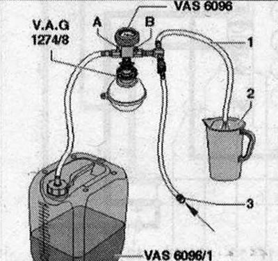
The exhaust air entrains a small amount of coolant, which must be collected. Close valves "A" and "B" by turning them perpendicular to the flow direction. Connect hose "3" to the compressed air line. Pressure: excess pressure 6...10 bar. Open valve "B" by turning it in the direction of the flow. A vacuum is created in the cooling system using an ejector pump; the indicator arrow should be in the green field. Open tap "A" briefly, for which turn it parallel to the flow direction so that the hose of the tank of the device for filling the cooling system is filled with coolant.
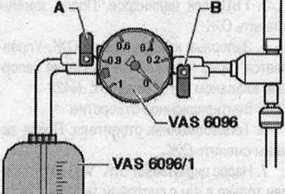
Close valve "A" again. Open valve "B" for 2 minutes. The ejector pump continues to create a vacuum in the cooling system; the indicator arrow should be in the green field. Close valve "B". The indicator arrow should remain in the green field, in which case the vacuum in the cooling system is sufficient for its subsequent filling. If the arrow is below the green field, then the previous operations should be repeated. If the vacuum decreases, check the cooling system for leaks. Remove the compressed air hose. Open valve "A". Due to the vacuum, the coolant coming out of the tank of the device for filling the cooling system fills the system. Remove the device for filling the cooling system from the adapter "V.A.G 1274/8" on the expansion tank. Put the tube on "V.A.G 1274/10" on the adapter "V.A.G 1274/8".
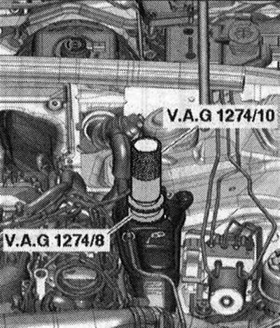
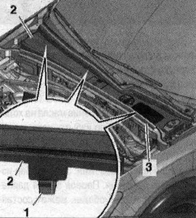
Fill with coolant until the cooling system tester tube is completely filled. If necessary, top up while bleeding air. Remove gasket "3". Release fastening clamps "1" from fasteners and remove water drain box cover "2".
Loosen and remove the coolant hose going to the heat exchanger so that the coolant comes out of the vent hole "arrow" in the coolant hose.
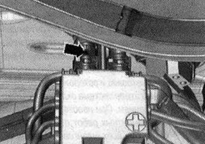
Place the coolant hose on the connection nipple and secure it. On vehicles with independent heating, switch on the heater for approx. 30 seconds. Close the expansion tank cap. Start the engine. Set the temperature for all zones to "HI" and, if possible, set the lowest ventilation level (= 0). Switch off the air conditioning compressor by pressing the AC button. The tester LED in the button should not light. Run the engine at 2000 rpm for 3 minutes. Let the engine idle until the 2 large coolant hoses on the radiator heat up. Run the engine at 2000 rpm for 2 minutes. Switch off and let the engine cool down. Install sound insulation. Check the coolant level. When the engine is cold, the coolant level should be at the "MAX" mark. If the engine has warmed up to operating temperature, the coolant level may be above the "MAX" mark.
Installation diagram of the coolant pipe and the coolant pump after switching off the engine "V51"
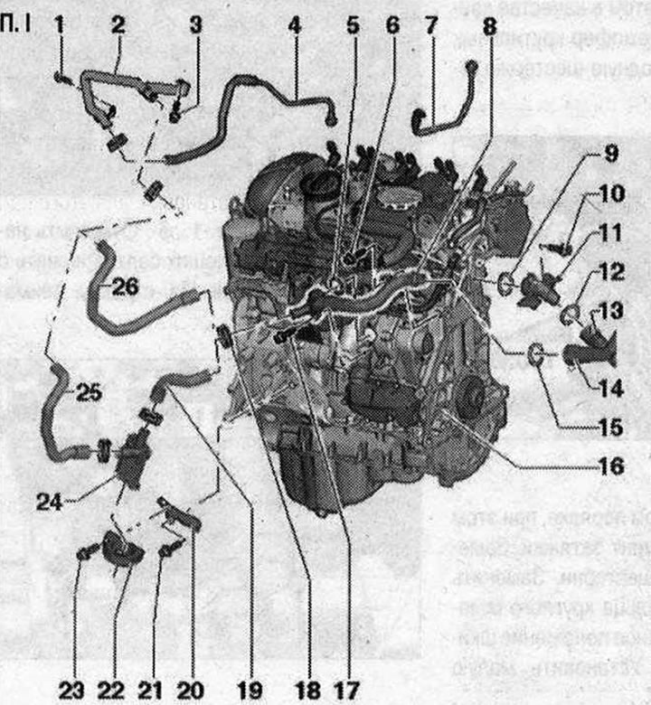
I
1/3. Bolt. 6 Nm; 2. Coolant supply pipe, front; 4. Return line of coolant from turbocharger; 5. Sealing ring. Replace; 6/10/17. Bolt. 9 Nm; 7. Coolant pressure line to turbocharger; 8. Small coolant pipe; 9. Sealing ring. Replace; 11. Fitting for engine cooling system hoses; 12. Sealing ring. Replace; 13. Cooling system hose To remove, loosen the clamp. Connect to the fitting; 14. Cooling system hose. To remove, loosen the clamp. Connect to the coolant pipe; 15. Sealing ring. Replace; 16. engine; 18. Hose clamp; 19. Cooling system hose (only in version for hot countries); 20. Bracket (only in version for hot countries); 21. Bolt (only in version for hot countries). 9 Nm; 22. Bracket (only in version for hot countries); 23. Bolt (only in version for hot countries). 4 Nm; 24. Coolant bleed pump after engine shutdown "V51" (only in version for hot countries); 25. Cooling system hose (only in version for hot countries); 26. Cooling system hose (not available for hot countries)
Coolant pump and thermostat
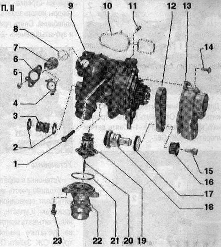
II 1. Bolt; 2. Sealing rings. Replace; 3. Connecting pipe; 4. Latches. For insertable design only. Check for secure fastening; 5. Bolt 4 Nm. For screw-on design only; 6. KP retainer. Only for screwed design; 7. Coolant temperature sensor "G62"; 8. Sealing ring. Replace; 9. Water pump. Remove the protective cap from the new pump; 10. Gasket. Replace; 11. Centering pin. 2 pcs.; 12. Coolant pump toothed belt; 13. Timing belt protection; 14. Bolt. 9 Nm; 15. Bolt. Left-hand thread. Replace. 10 Nm+ 90°; 16. Drive gear for toothed belt. Install in proper position; 17. Shaft seal; 18. Balance shaft; 19. Thermostat; 20. Centering pin; 21. Sealing ring. Replace; 22. Connecting pipe; 23. Bolt. 9 Nm
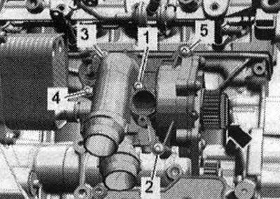
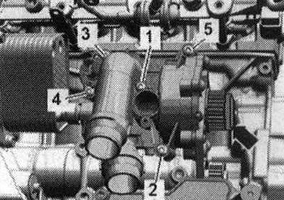
Coolant pump mounting bolt tightening sequence
Tighten the coolant pump bolts in sequence "1...5" to 9 Nm.
Removal the coolant temperature sensor "G62"
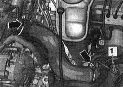
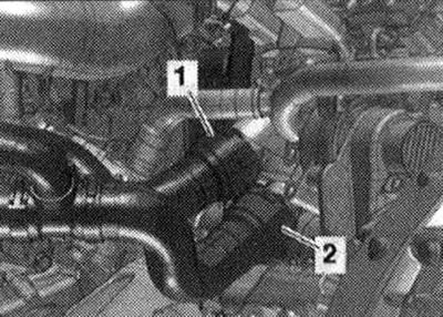
Cold engine. Briefly open the expansion tank cap to release residual pressure in the cooling system. Release the clamps of the "arrow" hose and remove the air duct hose.
"Pos. 1" do not take into account. Disconnect connector "1" of the throttle control unit "J338". Unscrew the bolts "arrows" and remove the throttle control unit "J338".
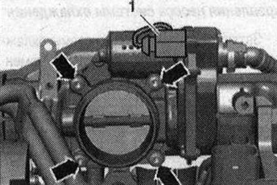
Remove the intake manifold support by unscrewing nut "2" and bolt "1".
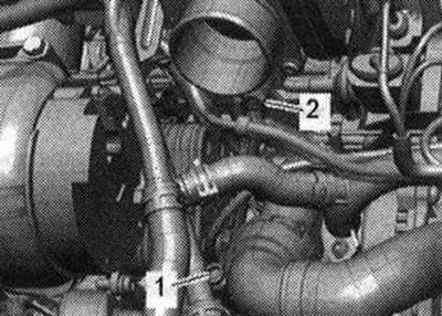
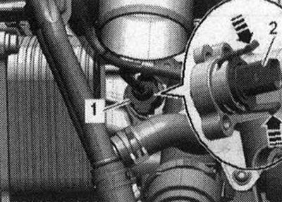
Depending on the version, different coolant temperature sensors "G62" can be installed.
Insertable design
Disconnect plug connector "1" of coolant temperature sensor "G62". Place a rag underneath to absorb leaking coolant. Remove latches, to do this press the stoppers "arrows". Remove coolant temperature sensor "G62" "pos. 2".
Screw-on design
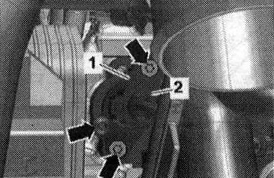
Disconnect plug connector "2" of coolant temperature sensor "G62".
Place a rag underneath to absorb the leaking coolant. Unscrew the bolts "arrows" and remove the mounting shield "1". Remove the coolant temperature sensor "G62".
Install
Installation in reverse order: replace the sealing rings. To avoid coolant loss, immediately insert a new coolant temperature sensor "G62" into the branch pipe. The hose nipples, air duct tubes and hoses must be cleaned of oil and grease before installation. Use clamps of the appropriate series to secure all hose connections. To ensure reliable fastening of the air duct hoses to the nipples, treat the threaded connections of the already used clamps with a rust remover. Install the intake manifold support. Install the throttle module "J338". Check the coolant level.
Removal the toothed belt of the cooling system pump
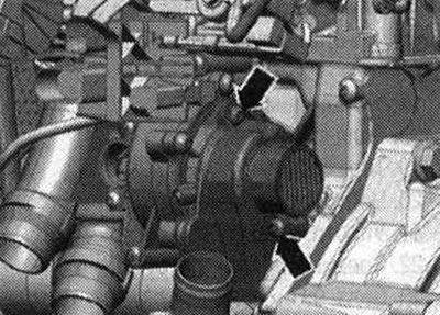
Remove the small pipe of the cooling system. Unscrew the bolts "arrows" and remove the protective cover of the toothed belt.
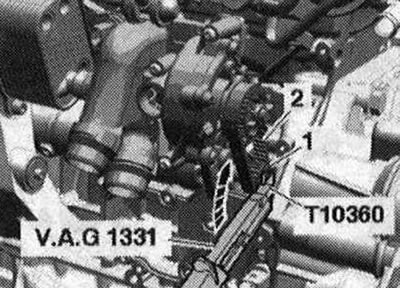
Risk of damage to the thread. The drive pinion bolt has a left-hand thread. Unscrew the bolt on the drive pinion "1" of the coolant pump using a torque wrench "V.A.G 1331" and the "T10360" attachment in a clockwise direction "arrow", using the torsional vibration damper as a counter-axe. Remove the drive gear "1" and the toothed belt "2".
Install
Installation in reverse order, taking into account the tightening torque. Replace the drive pinion bolt. Replace the gaskets and O-rings. Take into account the installation position of the toothed belt pulley. Install the small coolant pipe. Fill with coolant.
Removal the water pump
Remove the small coolant pipe. Remove the toothed belt of the coolant pump. Disconnect the electrical plug connection "1" of the throttle control unit "J338". Unscrew the bolts "arrows" and remove the throttle control unit "J338".
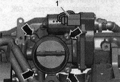
Disconnect plug connector "2" of coolant temperature sensor "G62". Ignore "Pos. 1" and "arrows".
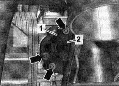
Remove the coolant hoses, to do this, lift the clamps "1" and "2", put the coolant hoses aside.
Unscrew bolts "1...5". Unfasten the coolant pump from the centering bolts and remove it from the oil radiator. Ignore the "arrow".
Install
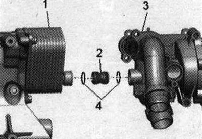
Install in reverse order, taking into account the tightening torque. Replace the gaskets and O-rings. Moisten the O-rings "4" with coolant, coolant. Check whether both centering pins are inserted into the cylinder block, insert if necessary. Insert the connecting element "2" into the oil cooler "1". Place the coolant pump "3" on the connecting part and the centering pins in the cylinder block.
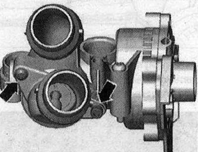
Tighten the coolant pump cover bolts. When installing a new coolant pump, remove the protective cap "arrow". Install the coolant pump toothed belt. Install the throttle control module "J338". Install the small coolant pipe. Connect the coolant hose using a coupling. Fill with coolant.
Removal the thermostat
Drain the coolant. Remove the coolant pump. Unscrew the bolts "arrows" and remove the connecting nipple.
Remove the thermostat.
Install
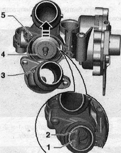
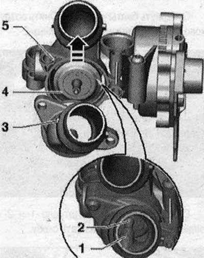
Install in reverse order, taking into account the tightening torque. Replace the gaskets and O-rings. Clean the sealing surface under the O-ring. Wet the O-rings with coolant, coolant. Insert thermostat "4" into housing "5" of the coolant pump and slightly turn forward "arrow". Carefully install branch pipe "3", while inserting centering pin "2" into guide "1".
Install the intake manifold support.
Fill with coolant.
Radiator, rim and radiator fan mounting
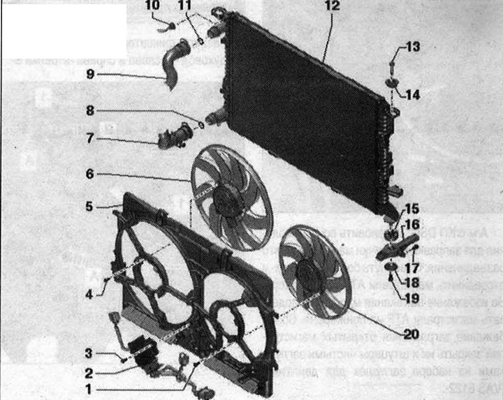
Radiator, rim and radiator fan mounting 1/4. Bolt. 5 Nm; 2. Used radiator fan "J293"; 3. Bolt 2.5 Nm; 5. Fan frame; 6. Radiator fan "V7"; 7/9. Cooling system hose. To remove, loosen the clamp. Connect to the radiator; 8/11. Sealing ring. Replace; 10. Cooling system hose to expansion tank; 12. Radiator. After replacement, drain the old and fill the cooling system with new coolant; 13. Locking bolt. Unlock with a screwdriver and remove; 14. Rubber buffer; 15. Rubber support for radiator; 16. Radiator console; 17. Bolt. 5.5 Nm; 18. Lining; 19. Bolt. 4.5 Nm; 20. Radiator fan 2 "V177"
Connecting the coolant hose with nipple connectors
Remove the old sealing ring "2" from the coolant hose "3". Moisten the new sealing ring with coolant and insert it into the coolant hose. Put the coolant hose onto the coolant pipe "1" until it clicks.
Press the coolant hose in again and pull the hose to ensure that the coupling is properly secured.
Removal the radiator together with the fan frame
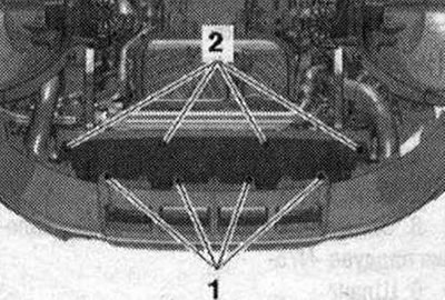
The radiator and fan frame are removed and installed together. The fan frame can be removed separately. Remove noise insulation screens "1" and "2". Remove the front bumper trim and bumper. Remove the intercooler.
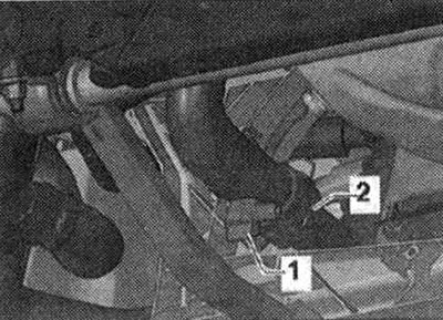
Install the tray for service cranes "VAS 6208" under the engine. Unscrew the threaded plug of the drain hole "1" and drain the coolant. Remove the coolant hose "2" from the radiator by pressing the fastening bracket.
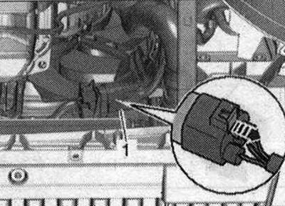
Risk of injury due to the radiator fan starting up by itself. Before starting work in the fan frame area, disconnect the plug connectors. Disconnect the electrical connector "1" of the radiator fan, move the locking device back "arrow" and press the stopper down.
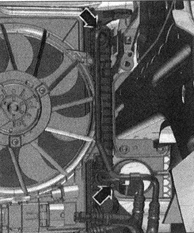
Cars with DSG gearbox: Install a device for filling and pumping out oil under the disconnection point. Unscrew the "arrow" bolts and disconnect the ATF lines from the radiator. To prevent ATF oil from leaking, tie the ATF lines to the side member. To prevent contamination of the open lines, close them and the fittings with clean plugs from the "VAS6122" engine plug kit.
All
Unscrew the "arrow" bolts. Remove the air duct "1" and the intermediate flange "2".
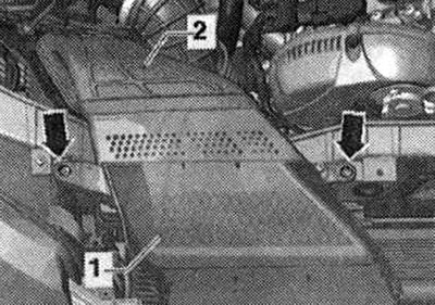
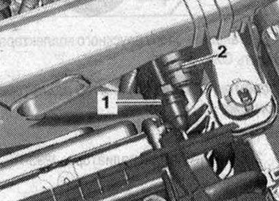
Remove the connecting nipple "1" and "2" from the radiator, to do this, loosen the clamp.
Disconnect the upper air duct "1" by unlocking the "arrow" fasteners.
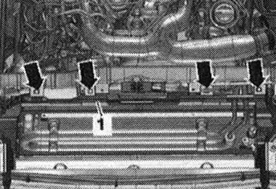
Release the clamps "arrow A" and remove the air duct "1" on the left and right "arrow B".
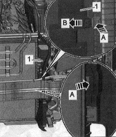
Vehicles with hydraulic steering: Open the retaining clips "arrow A" and move the power steering cooling coil "1" forward "arrow B". Remove the power steering cooling system hoses from the condenser upwards and place them on the engine.
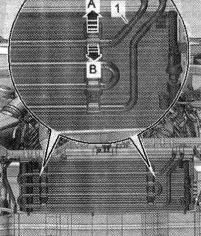
All
Loosen the radiator retainers on the left and right and remove them in the upward direction of the "arrow".
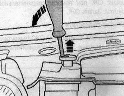
Unscrew bolts "1" on the left and right and remove the console and radiator from the radiator frame "arrow". Lower the radiator slightly.
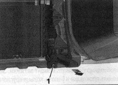
The second mechanic must unlock the fastening brackets "1" "in the direction of arrow A"; the first mechanic must remove capacitor "2" upwards from the mountings on the radiator "arrow B".
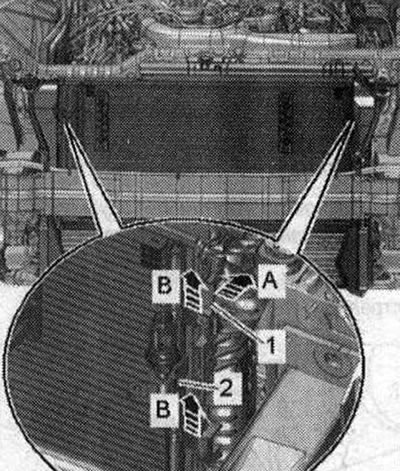
Tilt the condenser forward with the hoses connected. Remove the radiator. Press the locking tabs of the fan frame on the left and right "arrow" simultaneously and remove the fan frame from the radiator in an upward direction.
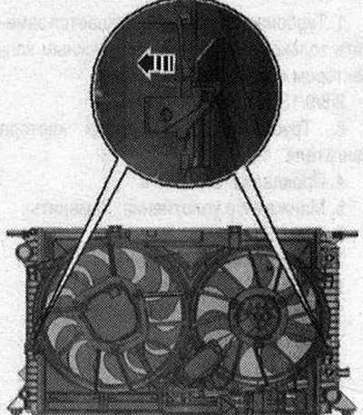
Install
Installation is in reverse order, in this case it is necessary to install the air duct of the intermediate flange of the air filter housing. Install the intercooler. Install the bumper and front bumper cover. Install the ATF lines. Fill with coolant. Check the transmission oil level. If the radiator was replaced, change the coolant.
Removal the fan frame
Remove the front noise insulation. Before working in the fan casing area, disconnect the electrical connectors. Disconnect the electrical connector "1" of the radiator fan by moving the lock back "arrow" and pressing the stopper down. Release the wiring harness.
Cars with DSG gearbox: Install a device for pumping out oil under the place of disconnection. Unscrew the "arrow" bolts and disconnect the ATF lines from the radiator.
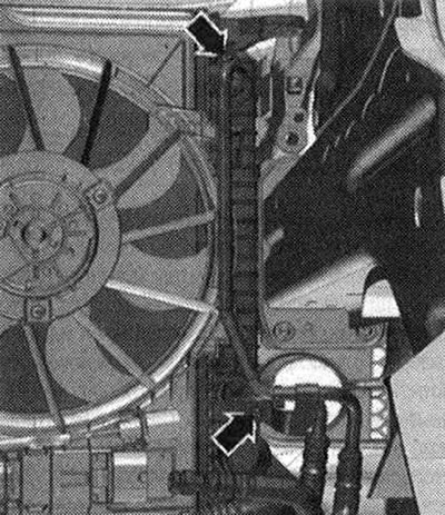
To prevent transmission oil leakage, secure the ATF lines on top of the side member. To prevent contamination from entering, close the disconnected lines and pipes on the intercooler with a clean plug from the plug kit for the "VAS 6122" engine.
All
Unscrew bolts "1" and "2", remove the noise insulation screen of the bumper trim in the rear direction.
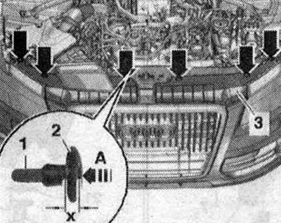
To remove the "arrow" spacer clamp, carefully press the clamping pin "1" by the dimension "x" until an audible click is heard into the "arrow A" spacer clamp. Dimension "x" = 5 mm. Remove the unlocked spacer clamp "2" with the clamping pin.
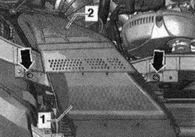
Unscrew the bolts "arrows". Remove the air duct "1" from the intermediate flange "2" of the air filter housing.
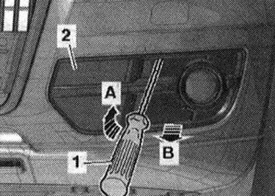
Unlock the lock "arrow A" with a screwdriver "1". Disconnect the air intake grille "2" from the bumper cover "arrow B". Repeat the work steps on the opposite side.
Disconnect the upper air duct "1" by unlocking the "arrow" latches.
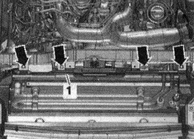
Release the clamps "arrow A" and tilt the air duct "1" on the left and right towards the center of the car "arrow B".
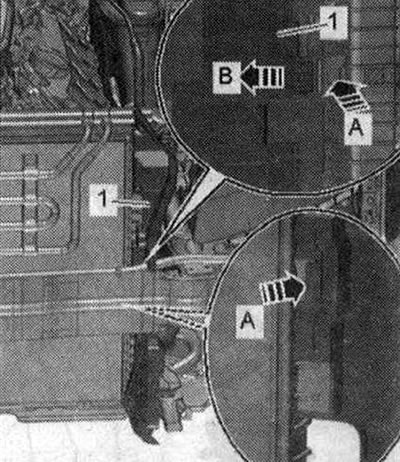
Remove the connecting nipple from the radiator, to do this, loosen the clamp "1". Do not take "Pos. 2" into account.
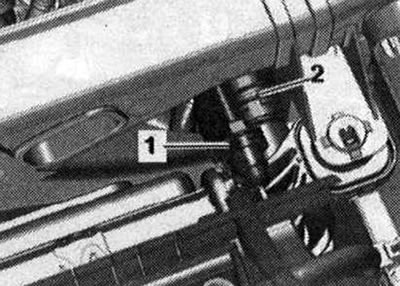
To the right and left, unlock both radiator mounting bolts and pull them up "arrows". Remove the radiator from the top in the forward direction.
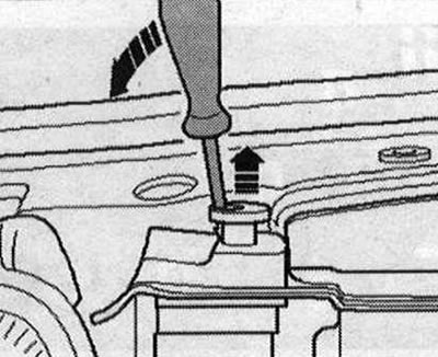
Press simultaneously the locking tabs of the fan frame on the left and right "arrow" and remove the fan frame from the radiator in the upward direction.
Install
Installation is in the reverse order, observing the tightening torque. Hose nipples, air duct tubes and hoses must be cleaned of oil and grease before installation. Use clamps of the appropriate series to secure all hose connections. Install the air duct on the intermediate flange of the air filter housing. Install the radiator frame trim and the noise insulation screen of the bumper trim. Tighten the ATF line bolts. Fill with coolant. Check the transmission oil level.