
Table of contents: Removal camshafts ↓ Install ↓ Replacing valve stem seals with the… ↓ Installation ↓
Note. The cylinder head and cylinder head cover may only be replaced together. After installing the camshafts, the engine must not be started for approximately 30 minutes. The hydraulic compensators must be settled (otherwise the valves will touch the pistons). After working on the valve mechanism, turn the engine by hand at least 2 revolutions to make sure that none of the valves are in contact with the piston. The seals and lip seals must be replaced.
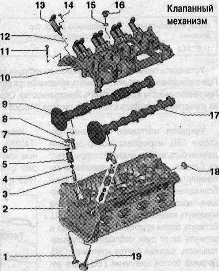
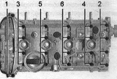
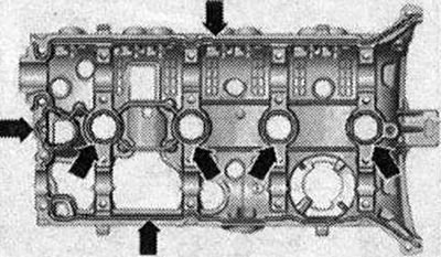
Valve mechanism 1. Exhaust valve. Cannot be processed, only lapping is allowed; 2. Cylinder head; 3. Valve guide bushing; 4. Oil seal. Replacement: with cylinder head installed, with cylinder head removed; 5. Valve spring; 6. Valve spring plate; 7. Valve cracker; 8. Hydraulic compensator. Do not change places. Lubricate the working surface with oil; 9. Exhaust camshaft. Checking radial runout using Plastigage measuring strips (roller levers removed). Radial clearance: 0.024...0.066 mm. Runout: max. 0.04 mm; 10. Cylinder head cover with integrated camshaft liners. Clean the sealing surface, modification of the sealing surface is not allowed. Remove the remains of the old sealant; 11. Bolt. Replace. Unscrew; 12. Sealing ring. Replace. Lubricate with oil; 13. Phase shifter actuator; 14. Bolt. 5 Nm; 15. Sealing ring. Replace. Lubricate with oil; 16. Plug; 17. Intake camshaft. Checking radial runout using Plastigage measuring strips (roller levers removed). Radial clearance: 0.024..0.066 mm. Runout: max. 0.04 mm; 18. Cover. Replace. Removal: with the cylinder head cover installed, use an awl to pry the cover from one side and remove it; 19. Inlet valve. Not subject to machining, only lapping is allowed; Disconnecting the cylinder head cover; Unscrew the cylinder head cover bolts in sequence 1...6.
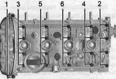
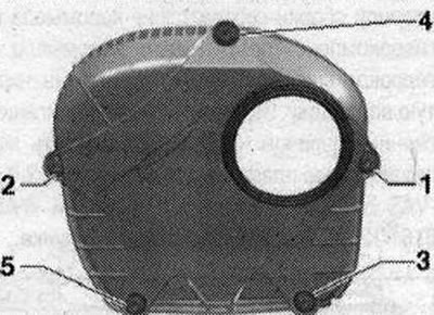
Tightening sequence of cylinder head cover bolts
Replace screws:
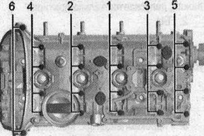
- 1. Tighten the bolts by hand in several stages in the sequence "1...6".
- 2. Tighten the bolts in the sequence "1...6" using a torque wrench to 8 Nm.
- 3. Tighten with a rigid wrench by 90° in the sequence "1...6".
Make sure that there are no distortions in the position of the cylinder head cover.
Removal camshafts
Note. The seating surfaces of the lower cylinder head cover and upper cylinder head are prohibited from being processed. The camshaft bearings are built into the cylinder head and cylinder head cover. Before removing the cylinder head cover, it is necessary to loosen the camshaft drive chain. After removing the cylinder head cover, the locking cap must be replaced. When reassembling, install all binders in the places where they were originally installed.
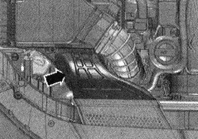
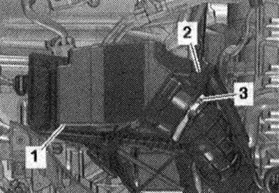
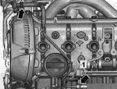
Bring to service position. Remove engine casing. Remove air duct "arrow".
Disconnect plug connector "2" of air flow meter "G70". Remove air duct hose from air flow meter "G70" by loosening hose clamp "3". Remove air filter housing "1" upwards.
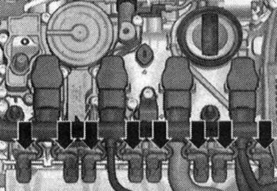
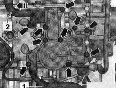
Unscrew the bolts of the plug block for the ignition coils. Remove the electrical connectors "arrows" from the adjustment elements of the timing phase adjustment system.
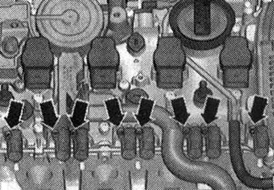
Unlock the "arrow" plugs and disconnect all the plugs from the ignition coils at the same time.
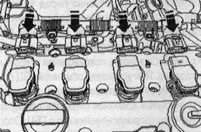
Remove the ignition coils using the "T40039" puller. Remove the adjusting elements of the timing phase adjustment system "arrows".
Disconnect the engine crankcase ventilation system hose "1". Unscrew the bolts "arrows", remove the engine crankcase ventilation system and disconnect it from the engine crankcase ventilation system hose "2" in the "direction of the arrow".
Disconnect the "arrow" wire. Disconnect the electrical connector "1" of the Hall sensor "G40".
Disconnect the plug of valve 1 of the variable valve timing system "N₂05" "1". Unscrew the "arrow" bolts and remove valve 1 of the timing phase change system "N₂05".
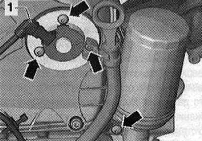
Unscrew bolts "1 through 5" and remove the right timing chain cover.
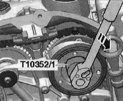
The distribution valve has a left-hand thread. Remove the distribution valve using the "T10352/1" tool in the "direction of the arrow".
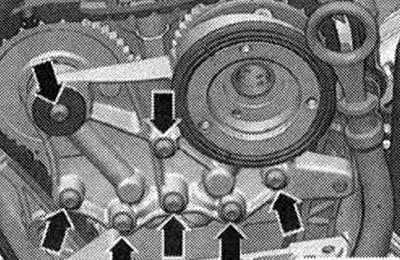
Unscrew the "arrow" bolts and remove the bearing housing.
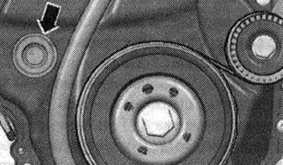
Turn the torsional vibration damper with the counter support "T10355" to the "TDC" position "arrow".
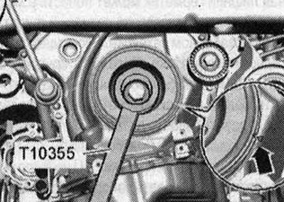
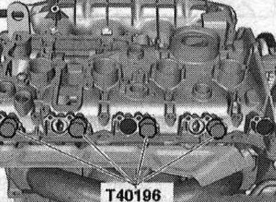
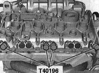
The notch on the vibration damper must be positioned opposite the arrow mark on the lower chain drive cover. Risk of engine damage. Mounting pins "T40196-must" be inserted only in the positions shown. Insert mounting pins "T40196" as shown in the figure. Turn the crankshaft in the direction of engine rotation by 2 turns.
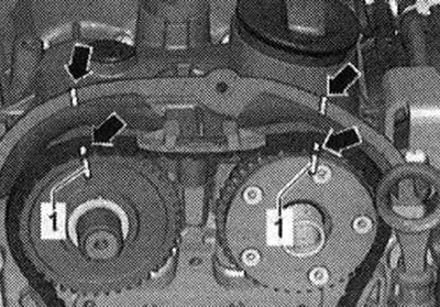
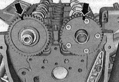
The engine should be at "TDC". Remove the mounting pins "T40196". Mark the camshaft drive chain and cylinder head "arrows" according to the marks on the chain sprockets "1" with a waterproof marker.
Unscrew the "arrow" plug.
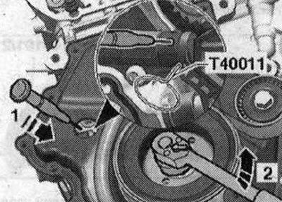
Raise the chain tensioner locking wedge by inserting a marking needle or a suitable screwdriver into the tensioner hole in the "direction of arrow 1". Turn the crankshaft against the direction of engine rotation in the "direction of arrow 2" and secure with pin "T40011".
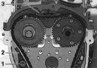
The intake camshaft goes into rotation in the direction of engine rotation. Unscrew bolt "1" and move tension bar "2" down. Remove the upper chain guide "3" by unlocking the lock with a screwdriver and pressing the guide forward. Remove the camshaft drive chain.
Risk of damage to valves and piston crowns. If the camshaft drive chain is removed from the cylinder head, the crankshaft must not be turned any further. Remove the high-pressure pump. Remove the vacuum pump. Loosen the cylinder head cover bolts in the sequence "1...6". Remove the cylinder head cover. Remove the camshafts.
Install
There should be no oil or grease on the sealing surfaces. The pistons should not be at TDC. Check that all rocker arms are correctly installed on the valve stem tails. Remove any remaining sealant on the cylinder head with a flat scraper. Remove any remaining sealant from the cylinder head cover groove and from the sealing surfaces, for example, with a drill with a rotating plastic brush attachment. Clean the seating surfaces; there should be no oil or grease on them. Lubricate the working surfaces of the camshafts with oil. Insert the "T40191" spacers into the camshaft, as shown in the figure, if necessary, move the sliders to the correct position.
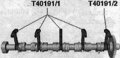
If available, use a second set of spacers "T40191" or insert "T40191/1". Place the camshafts in the cylinder head, the "arrows" markings must be vertical.
Check the alignment of the camshaft arrows.
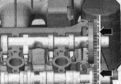
Cut off the tube tip along the front mark (About 2mm holes). Apply silicone sealant to the clean seating surface of the cylinder head cover as shown in the figure "arrows". Thickness of the sealant strip: 2-3 mm.
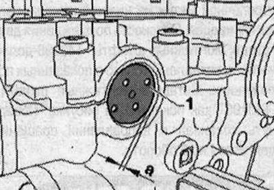
After applying the silicone sealant, install the cylinder head cover within 5 minutes. The sealant bead should not be thicker than the specified width, otherwise excess sealant may get into the oil pan and clog the mesh filter in the oil intake pipe. Observe the expiration date of the sealant. Put the cover on the cylinder head. Replace the cylinder head cover bolts. Tighten the bolts in several stages, observing the tightening sequence of the cylinder head cover fastening bolts. Make sure that there are no distortions in the position of the cylinder head cover. Press in the locking cover "1" without sealant using the mandrel "T10174". "a": 1-2 mm.
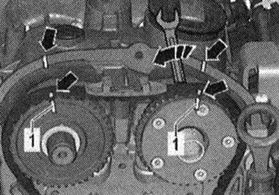
Turn the vibration damper with the counter-support "T10355" to the "TDC" position "arrow". The notch on the vibration damper should be located opposite the arrow mark on the lower cover of the chain drives. The marked links of the timing chain should be installed according to the marks on the sprockets and cylinder head. Turn the intake camshaft with a wrench in the "direction of the arrow" and put on the drive chain. The marks on the camshaft chain and cylinder head "arrows" should coincide with the marks on the chain sprocket "1".
Mount the bearing housing and screw in the "arrow" bolts by hand. Remove the "T40011" locking pin. Tighten the "arrow" bolts of the bearing housing.
Install the distribution valve. Insert the mounting pins "T40196" as shown in the figure.
Turn the crankshaft in the direction of engine rotation by 4 turns. Remove the mounting pins "T40196". Install the upper cover of the drive chain. Install the vacuum pump. Install the high-pressure pump. Return to the service position. Install the air filter housing. Installation in the reverse order.
Replacing valve stem seals with the cylinder head installed
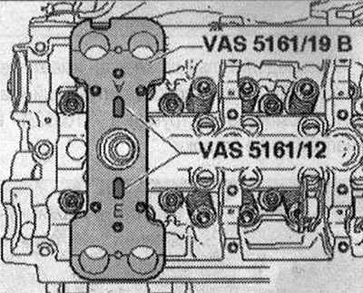
Remove the camshafts. Mark the alignment of the rocker arm and hydraulic compensator for reassembly. Remove the rocker arm with hydraulic compensators and place it on a clean lining. Unscrew the spark plugs with the spark plug wrench "3122 B". Screw on the guide plate for 2.0 l engines "VAS 5161/19B" with knurled screws "VAS 5161/12" to the cylinder head, as shown in the figure.
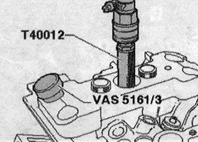
Bring the piston of the corresponding cylinder to the "bottom dead center". Screw the adapter "T40012" into the threaded hole of the spark plug. Turn on the compressed air supply with an excess pressure of at least 6 bar. Separate the tightly seated valve crackers using a mandrel "VAS 5161/3" and a plastic hammer.
For the intake side
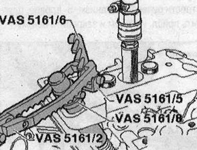
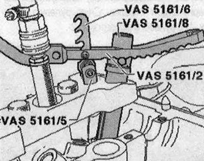
Screw in the device "VAS 5161/6" with hanging fork "VAS 5161/5" into the middle thread of the guide plate for 2.0 or 3.0 l FSI engines "VAS 5161/19B". Insert the mounting cartridge "VAS 5161/8" into the guide plate for 2.0 or 3.0 l FSI engines "VAS 5161/19B". Connect the push-in fork "VAS 5161/2" to the device "VAS5161/6".
For the release side
Screw in the device "VAS 5161/6" with hanging fork "VAS 5161/5" into the external thread of the guide plate for 2.0 or 3.0 l FSI engines "VAS 5161/19B". Press the mounting cartridge "VAS 5161/8" and simultaneously turn the knurled screw of the mounting chuck "VAS 5161/8" to the right until the ends enter the valve pins. Slightly turn the knurled screw back and forth, due to this the valve pins are released and captured by the mounting chuck. Release the pressure fork "VAS 5161/2". Remove the mounting cartridge "VAS5161/8".
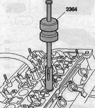
Remove the oil seals using the puller "3364".
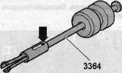
If, due to lack of space, it is not possible to use the valve stem seal puller "3364", press out the "arrow" pin with a punch and remove the attachment.
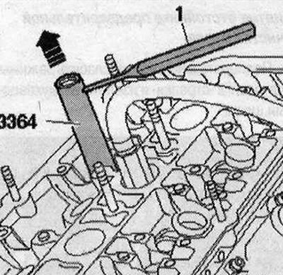
Install the lower part of the valve stem seal puller "3364" onto the valve stem seal. Insert the punch -1 into the hole in the lower part of the puller. Move the mounting lever under the puller and remove the valve stem seal "arrow".
Installation
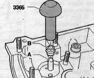
To avoid damaging the new valve stem seals "B", place the plastic sleeve "A" on the valve stem. Lubricate the working edge of the valve stem seal "B" with oil, insert into the pressing device "3365" and carefully press into the guide sleeve. Remove the plastic sleeve "A".
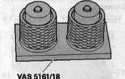
Insert the valve spring and valve spring plate. Install the assembly and disassembly device "VAS 5161" as shown. After removing the valve crackers from the assembly cartridge, they must first be inserted into the assembly device "VAS 5161/18". Press the mounting cartridge "VAS 5161/8" on top of the mounting device and remove the valve crackers.
Press the mounting chuck "VAS 5161/8" push fork "VAS 5161/2", turn the knurled screw of the mounting chuck in all directions and pull it upwards. Release the push fork "VAS 5161/2" with the knurled screw pulled out. Remove the mounting and dismounting device "VAS 5161". Installation is in the reverse order. Install the camshafts.