
Table of contents: Valve sizes ↓ Removal and installation camshafts ↓
Note: The cylinder head and cylinder head cover may only be replaced together. After installing the camshafts, the engine must not be started for approximately 30 minutes. The hydraulic lifters must be settled (otherwise the valves will touch the pistons). After working on the valve mechanism, carefully turn the engine by hand for at least 2 revolutions to ensure that no valve comes into contact with the piston during starting. Seals and lip seals must be replaced.
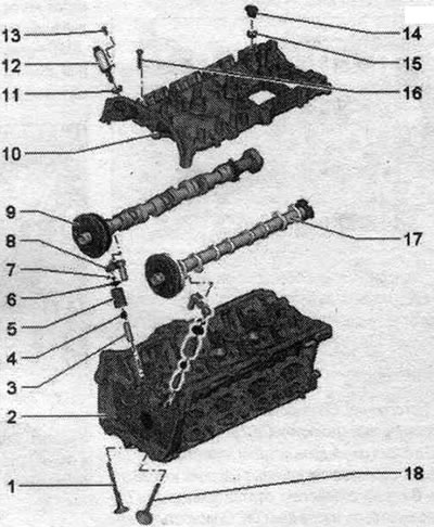
1. Exhaust valve: cannot be machined, only lapping is allowed. 2. Cylinder head. 3. Valve guide: check. 4. Valve stem seal: replace. 5. Valve spring. 6. Valve spring plate. 7. Valve cracker. 8. Hydraulic compensator: do not change places, lubricate the working surface with oil. 9. Exhaust camshaft: Checking radial runout using Plastigage measuring strips (roller levers are dismantled); radial clearance: 0.024...0.066 mm, runout: max. 0.04 mm. 10. Cylinder head cover: with integrated camshaft bearings; clean the sealing surface, reworking of the sealing surface is not allowed; remove any remaining old sealant. 11. Sealing ring: replace, lubricate with oil. 12. Executive element of the phase shifter. 13. Bolt: 5 Nm. 14. Sealing ring: replace, lubricate with oil. 15. Plug. 16. Bolt: replace. 17. Intake camshaft: check radial runout using Plastigage measuring strips (roller levers are dismantled); radial clearance: 0.024...0.066 mm, runout: max. 0.04 mm. 18. Inlet valve: cannot be machined, only lapping is allowed.
Disconnecting the cylinder head cover
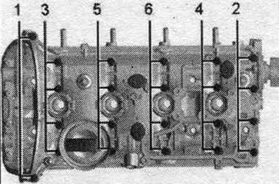
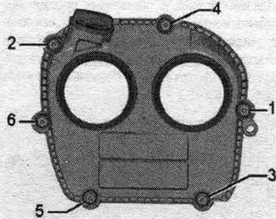
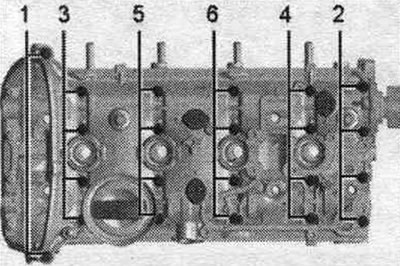
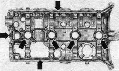
Loosen the cylinder head cover bolts in sequence. 1...6.
Tightening sequence of cylinder head cover bolts
Replace the bolts.
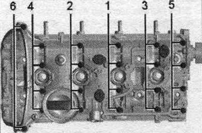
1. Tighten the bolts by hand in several stages in sequence. "1...6".
2. Tighten the bolts in sequence. "1...6" with a torque of 8 Nm.
3. Tighten with a rigid wrench by 90° in sequence. "1...6".
Note: Ensure that the cylinder head cover is not tilted.
Valve sizes
Note: It is prohibited to process the intake and exhaust valves. Only lapping is allowed.
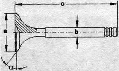
| Size | Inlet valve | Exhaust valve |
| Diameter a, mm | 33,85±0,10 | 28,0±0,1 |
| Diameter b, mm | 5,98±0,01 | 5,96±0,01 |
| s, mm | 104,0±0,2 | 101,9 ±0,2 |
| α,° | 45 | 45 |
Removal and installation camshafts
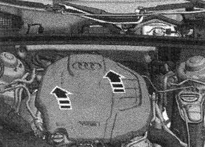
It is prohibited to process the seating surfaces of the lower cylinder head cover and the upper cylinder head. The camshaft bearings are integrated into the cylinder head and head cover. Before removing the head cover, the camshaft drive chain must be loosened. When reassembling, install all binders in the places where they were originally installed. Bring to service position. Remove the engine cover "arrows". Remove the lower air duct together with the hose.
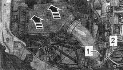
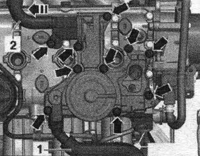
Disconnect hose "1" from the air filter. Release the air intake pipe "2". Remove the air filter housing. filter upwards with the "arrows" pointing upwards. Seal off the turbocharger using the plugs from the "VAS 6122" engine plug kit.
Remove the "arrow" plugs from the adjusting elements of the system. regulation of the timing phases.
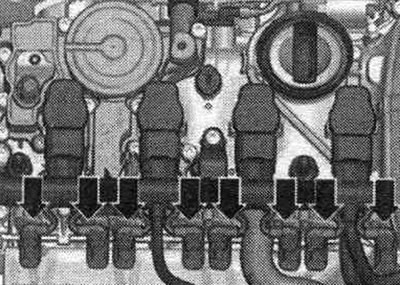
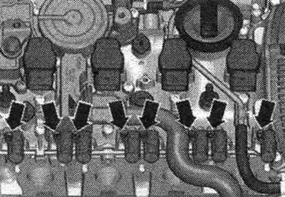
Remove the lambda probe connector "1" from the holder. Unlock and simultaneously disconnect all connectors from the coils. Unscrew the mounting screws and remove the ignition coils.
Remove the adjusting elements of the system. "arrow" timing phase adjustment.
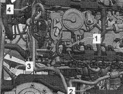
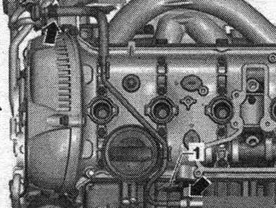
Disconnect the system hose. crankcase ventilation system "1". Unscrew the bolts "arrows", remove the crankcase ventilation system and disconnect it from the hose "2" of the crankcase ventilation system in the "direction of the arrow".
Disconnect the "arrow" wire. Disconnect the electrical. plug "1" of the Hall sensor "G40".
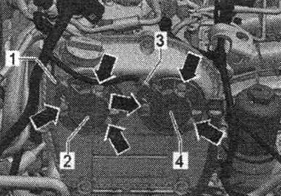
Disconnect connector "1" from valve 1 of the exhaust valve timing adjuster "N318" and connector "2" from valve 1 of the intake valve timing adjuster "N205". Unscrew the bolts "arrows" and remove valve 1 of the intake valve timing adjuster "N205" and valve 1 of the exhaust valve timing adjuster "N318".
Unscrew bolts "1...6" and remove the upper cover of the drive chain.
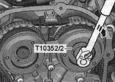
The control valves have left-hand threads. Remove the control valves using the puller "T10352/2" in the "direction of the arrow".
Unscrew the "arrow" bolts and remove the bearing housing.
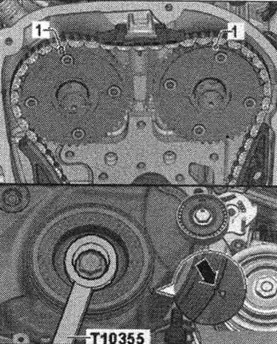
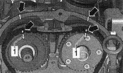
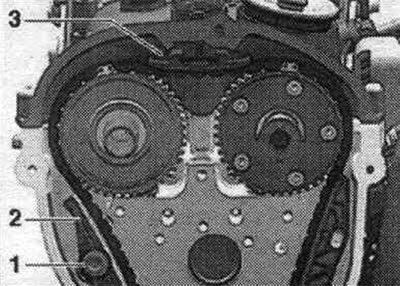
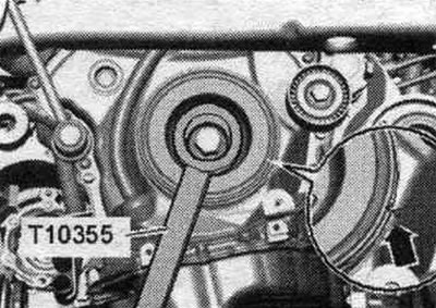
Using the support "T10355", turn the torsional vibration damper and set it to "TDC" "arrow". The notch on the vibration damper must be opposite the arrow mark on the lower timing chain cover. The "1" marks on the camshafts must face upwards.
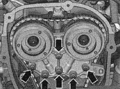
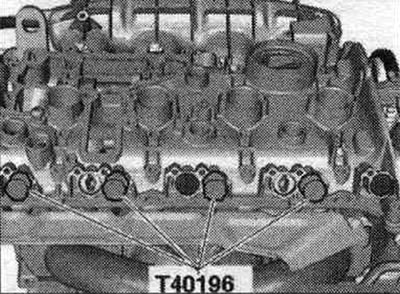
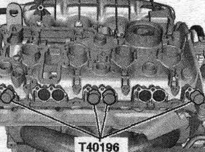
Mounting pins "T40196" must only be inserted in the positions shown. Insert mounting pins "T40196" as shown in the figure. Rotate the crankshaft 2 revolutions in the direction of engine rotation. The engine should be at TDC. Remove the mounting pins "T40196".
Mark the camshaft drive chain and cylinder head "arrows" to the marks on the chain sprockets "1" with a waterproof marker.
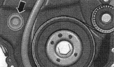
Remove the "arrow" plug.
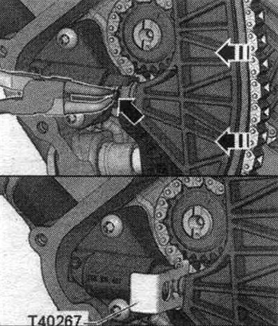
Loosening the chain tensioner is shown with the drive chain cover removed. Compress the chain tensioner retaining ring "arrow." Rotate the engine by the crankshaft counterclockwise, counteracting the engine's direction of rotation, and secure the chain tensioner using the "T40267" locking tool.
The intake camshaft begins to rotate in the direction of engine rotation. Remove bolt "1" and move tension bar "2" downward. Remove upper chain guide "3" by unlocking the locking mechanism with a screwdriver and pushing the guide forward. Remove the camshaft drive chain from the sprockets. If the camshaft drive chain is removed from the cylinder head, the crankshaft cannot be turned any further.
Remove the high pressure pump. Remove the vacuum pump. Unscrew the cylinder head cover bolts in sequence. "1...6". Remove the cylinder head cover. Remove the camshafts.
Installation
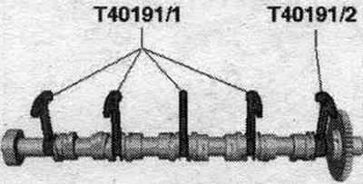
The sealing surfaces must be free of oil and grease. The pistons should not be at TDC. Check that all rocker arms are properly seated on the valve stem ends. Remove any remaining sealant from the cylinder head using a flat scraper. Remove any remaining sealant from the cylinder head cover groove and sealing surfaces, for example, using a drill with a rotating plastic brush attachment. Clean the sealing surfaces; there should be no oil or grease on them. Lubricate the working surface of the camshafts with oil. Insert the "T40191" spacers into the camshaft as shown in the figure; if necessary, move the sliders to the correct position. If available, use 2 sets of spacers "T40191" or insert "T40191/1".
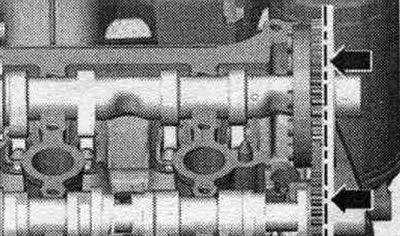
Place the camshafts in the cylinder head, the "arrow" markings must be in a vertical position.
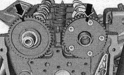
Check the alignment of the camshaft arrows.
Cut off the tip of the tube along the front mark (hole diameter is about 2 mm). Apply silicone sealant to the clean mating surface of the cylinder head cover as shown in the illustration "arrows". Sealant bead thickness: 2 - 3 mm. After applying the silicone sealant, install the cylinder head cover within 5 minutes. The sealant bead must not be thicker than the specified width, otherwise excess sealant may enter the oil pan and clog the screen filter in the oil pickup tube. Take into account the expiration date of the sealant.
Place the cover on the cylinder head. Replace the cylinder head cover bolts. Tighten the bolts in several stages. Make sure that there is no distortion in the position of the cylinder head cover. Turn the vibration damper with counter-support "T10355" to the "TDC" position "arrow". The notch on the vibration damper must be opposite the arrow mark on the lower timing chain cover. Timing chain links that are marked must be installed in accordance with the markings on the sprockets. Set the colored links of the camshaft drive chain opposite the marks on the sprockets; to do this, turn the camshafts using the "T40266" tool.
Place the bearing housing on the bearing and tighten the "arrow" bolts by hand. Remove the "T40267" locking pin. Tighten the "arrow" bolts of the bearing housing. Install the distribution valve. Insert mounting pins "T40196" as shown in the figure. Rotate the crankshaft 4 revolutions in the direction of engine rotation. Remove the mounting pins "T40196".
Install the upper drive chain cover. Install a vacuum pump. Install a high pressure pump. Return to service position. Install the air casing. filter. Installation is in reverse order.