Repair Chevrolet Repair Toyota Repair Honda Repair AvtoVAZ Repair Mercedes-Benz Repair BMW Repair Opel
Home  |  Contacts  |  Sitemap  |    
English Русский
Български
Беларускі
Український
Српски
Hrvatski
Română
Polski
Slovenský
Magyar
AudiManual.ru


  • AUDI 80
  • AUDI 100
  • AUDI A3
  • AUDI A4
  • AUDI A6
  • AUDI A8
  • AUDI Q
  • OTHER
  • ARTICLES
B8 (2007-2015) B7 (2004-2008) B6 (2000-2006) B6 (2000-2006, petrol) B5 (1994-2001) B5 (1994-2001, petrol)

Timing chain covers, timing valves (Audi A4 B8)

  • Home
  • Audi A4
  • B8 (2007-2015)
  • Power unit
  • Petrol engines 1.8 l
  • Timing chain covers, timing valves
            0
Table of contents: Timing chain covers, timing valves ↓ Removal and installation the upper… ↓ Replacing the lower timing chain… ↓

Timing chain covers, timing valves


1. Sealing ring: replace, lubricate before installation. 2. Oil dipstick guide tube. 3/4. Bolt: 9…

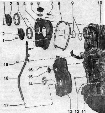
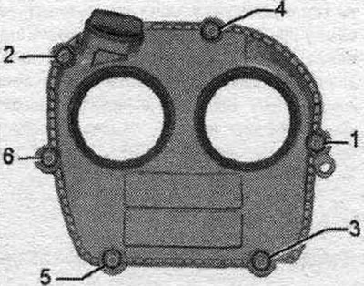
1. Sealing ring: replace, lubricate before installation. 2. Oil dipstick guide tube. 3/4. Bolt: 9 Nm. 5. Valve 1 of the exhaust valve timing adjuster "N318". 6. Sealing cuff: lubricate with oil before installation; if damaged, replace. 7. Valve 1 for adjusting the timing phases "N205". 8. Sealing cuff: lubricate before installation, replace if damaged. 9. Bolt. 10. Upper drive chain cover. 11. Gasket: replace if damaged. 12. Sealing ring: replace, lubricate before installation. 13. Dowel pins: centering the cover. 14. Lower timing chain cover. 15. Bolt: replace. 16. Vibration damper shaft gasket. 17. Plug: replace.


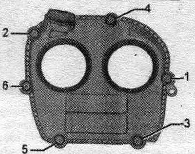
Upper timing chain cover - sequence, tightening


Tighten bolts "1...6" in the specified sequence.

Tighten bolts «1...6» in the specified sequence.


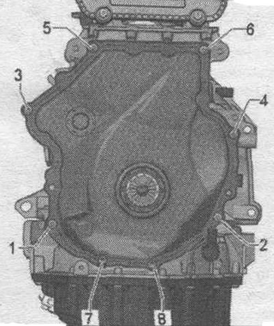
Lower chain drive cover - tightening sequence


Tighten bolts "1...8" in 2 stages in the specified order.


Tighten bolts «1...8» in 2 stages in the specified order.


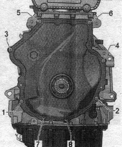
1. Tighten the bolts to 4 Nm.

2. Tighten the bolts by 45°.

Removal and installation the upper timing chain cover


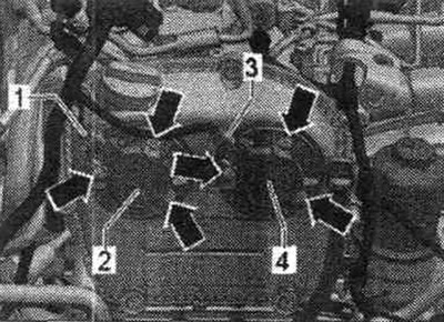
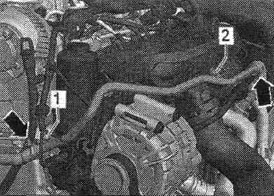
Disconnect connector "1" from valve 1 of the exhaust valve timing adjuster "N318" and connector "2" from valve 1 of the intake valve timing adjuster "N205". Unscrew the bolts "arrows" and remove valve 1 of the intake valve timing adjuster "N205" and valve 1 of the exhaust valve timing adjuster "N318".

Disconnect connector «1» from valve 1 of the exhaust valve timing adjuster «N318» and connector «2»…


Unscrew bolts "1...6" and remove the upper cover of the drive chain.

Unscrew bolts «1...6» and remove the upper cover of the drive chain.


Installation


Installation in reverse order. Replace the seal. o-rings. Lubricate the lip seals and gaskets. rings with oil. Install the upper timing chain cover, sequence, tightening. Install the intake camshaft adjuster valve 1 "N205" and the exhaust camshaft adjuster valve 1 "N318".


Replacing the lower timing chain cover


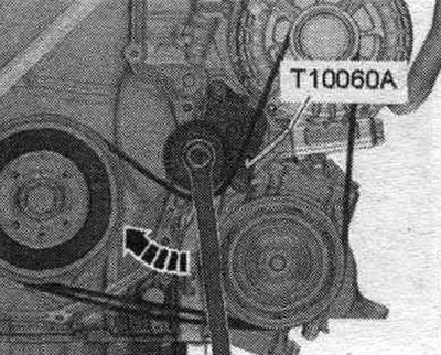
Remove the front sound insulation. Remove the front bumper trim and bumper. Bring to service position. Before removing the poly V-belt, mark the direction of movement with chalk or a felt-tip pen for subsequent installation. To loosen the poly V-belt, turn the tensioner in the direction of the arrow. Secure the tensioner with the T10060 A locking pin. Remove the poly V-belt.

Remove the front sound insulation. Remove the front bumper trim and bumper. Bring to service…


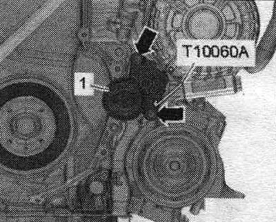
Unscrew the "arrow" bolts and remove the tensioner "1" of the poly V-belt from the additional holder. units.

Unscrew the «arrow» bolts and remove the tensioner «1» of the poly V-belt from the additional…


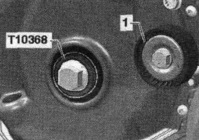
Turn the vibration damper with counter-support "T10355" to the "TDC" position "arrow". The notch on the vibration damper must be opposite the arrow mark on the lower timing chain cover. Unscrew the damper bolt using the T10355 counter support. Remove the vibration damper. To avoid damaging the gear engagement, screw in the damper bolt only with the T10368 mandrel.


Turn the vibration damper with counter-support «T10355» to the «TDC» position «arrow». The notch on…


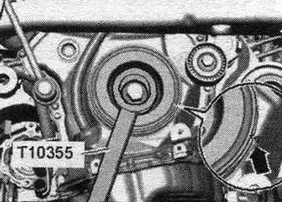
Reinstall the damper bolt and the T10368 drift. To avoid adjusting the timing, do not rotate the crankshaft past the TDC position with the damper bolt removed.

Reinstall the damper bolt and the T10368 drift. To avoid adjusting the timing, do not rotate the…


Unscrew bolt "1" and remove the dipstick guide tube from the drive chain cover.

Unscrew bolt «1» and remove the dipstick guide tube from the drive chain cover.


Unscrew screws "1...8". Remove the lower cover of the drive chain.


Unscrew screws «1...8». Remove the lower cover of the drive chain.


Installation


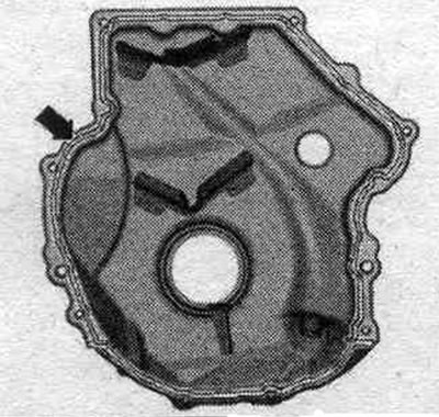
Take into account the expiration date of the silicone sealant. The lid must be installed within 5 minutes after applying the silicone sealant. Replace bolts that were tightened with additional tightening. Replace all seals, gaskets and self-locking nuts. Remove any remaining sealant from the cylinder block using a flat scraper. Clean the sealing surfaces from oil and grease. Check that both dowel pins are present to center the "arrow" cover.

Take into account the expiration date of the silicone sealant. The lid must be installed within 5…


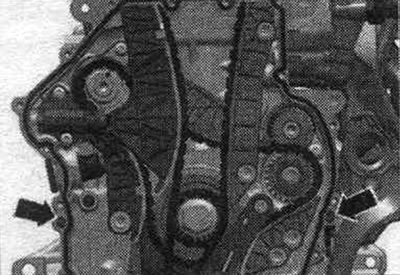
Cut off the tip of the tube along the front mark (hole diameter is about 3 mm). Apply sealant to the clean seating surface of the new cover as shown in the figure. Sealant bead thickness: 2-3 mm. The sealant bead should not be thicker than the specified width, otherwise excess sealant may enter the oil pan and clog the mesh filter in the oil intake pipe.


Cut off the tip of the tube along the front mark (hole diameter is about 3 mm). Apply sealant to…


Install the cover immediately and tighten the bolts. After installing the cap, allow the sealant to dry for about 30 minutes. Only then can you add oil. Install the tensioner for the poly V-belt. Install the poly V-belt. Return to service position. Install the front bumper cover and bumper. Install the front noise insulation screen. Check the oil level.
The article was checked by auto expert Timur Bazhenov
This article is available at russian, bulgarian, belarusian, ukrainian, serbian, croatian, romanian, polish, slovak, hungarian

Share information:
Previous articles
Audi A4 B8: Petrol engines 1.8 l
Next articles

Balance shafts — removal and installation
Cylinder block from the gearbox side
Cylinder block from the belt pulley side — attachments
1.8L Petrol Engine (CJEB) — Removal and Installation
Chain drive — removal and installation
Cylinder head — removal and installation
Valve mechanism — disassembly, assembly
Lubrication system


Similar articles on other Audi car models:
Timing Belt and Sprockets — Removal, Check and Installation Audi 80 B3 (1986-1991, petrol)
Replacing the timing belt of a 4-cylinder engine with five… Audi 100 C4 (1990-1994)
Checking the timing belt for damage, measuring wear Audi A3 Type 8L (1996-2003)
Timing chain — removal and installation Audi A6 C5 Allroad (1999-2005)
Replacing the timing belt Audi A8 D2 (1994-2002)
Timing chain covers, valve 1 of timing phase adjustment «N205» Audi Q5 Type 8R (2008-2017)
Timing Belt (4-cyl. petrol engine) Audi A2 (1999-2005)
Link to this page in different formats


Visitor comments

No comments yet


How much will 50 + 40 =


A4(B8, 2007-2015) 
  • General information
  • Operating instructions
  • Power unit
  • Petrol engines 1.8 l
  • Petrol engines 1.8/2.0 l
  • Petrol engines 3.0 l
  • Petrol engines 3.2 l
  • Fuel system (petrol)
  • Diesel engines 2.0 l (CA*)
  • Diesel engines 2.0 l (CJCB)
  • Diesel engines 2.7/3.0 l
  • Diesel engines 3.0 l
  • Fuel system (diesel)
  • Transmission
  • Manual gearbox 0B1
  • Manual gearbox 0B2
  • Manual gearbox 0B3
  • Manual gearbox 0B4
  • Automatic transmission 0B5
  • Automatic transmission 0B6
  • Automatic transmission 0AW
  • All-wheel drive system
  • Chassis
  • Front suspension
  • Rear suspension
  • Brake system
  • Steering system
  • Body
  • Exterior
  • Interior
  • Seats
  • Doors, locks and windows
  • Security system
  • Heating and air conditioning
  • Electrical equipment
  • Audio system
  • Power devices
  • Equipment and devices
  • Lighting and lamps
  • Electrical circuits
 
A4(B7, 2004-2008) 
  • General information
  • Introduction to manual
  • Troubleshooting
  • Operating instructions
  • Maintenance
  • Power unit
  • Petrol engines 2.0 (ALT)
  • Petrol engines 2.0 (TFSI)
  • Petrol engines 1.8 (MPI)
  • Diesel engines
  • Cooling system
  • Air conditioner
  • Fuel and exhaust system
  • Ignition system
  • Starting and charging
  • Transmission
  • Clutch
  • Manual gearbox
  • Automatic gearbox
  • Drive shafts
  • Chassis
  • Brake system
  • Front suspension
  • Rear suspension
  • Steering
  • Body
  • Exterior
  • Interior
  • Electrical equipment
  • Equipment and devices
  • Lighting and signaling
  • Windscreen wipers and washers
  • Electrical diagrams
  • Electrical diagrams (since 2007)
 
A4(B6, 2000-2006) 
  • General information
  • Vehicle Description
  • User manual
  • Maintenance
  • Power unit
  • Gasoline engine
  • Diesel engine
  • Lubrication system
  • Cooling system
  • Supply system
  • Injection system
  • Exhaust system
  • Ignition and control
  • Transmission
  • Gear box
  • Clutch and drive shafts
  • Chassis
  • Brake system
  • Car suspension
  • Steering
  • Body
  • Heating and ventilation
  • Exterior (external elements)
  • Interior (internal elements)
  • Electrical equipment
  • Power devices
  • Lighting and appliances
  • Electrical circuits
 
A4(B6, 2000-2006, petrol) 
  • General information
  • Introduction to the guide
  • Car care
  • Power unit
  • Engine repair
  • Lubrication system
  • Cooling system
  • Injection and control system
  • Ignition system
  • Power and exhaust system
  • Transmission
  • Clutch and drive shafts
  • Car gearbox
  • Chassis
  • Suspension and wheels
  • Steering
  • Brake system
  • Body
  • Interior
  • Exterior
  • Electrical equipment
  • Equipment and devices
  • Lighting and signaling
  • Power devices
  • Electrical circuits
 
A4(B5, 1994-2001) 
  • General information
  • Introduction to the guide
  • Car care
  • Maintenance (gasoline)
  • Maintenance (diesel)
  • Power unit
  • Gasoline engines
  • Diesel engines
  • Engine overhaul
  • Cooling system
  • Fuel injection (gasoline)
  • Fuel system (diesel)
  • Exhaust system
  • Ignition system
  • Transmission
  • Clutch
  • Mechanical gearbox
  • Automatic gearbox
  • Drive shafts
  • Chassis
  • Brake system
  • Car suspension
  • Steering
  • Body
  • Exterior
  • Interior
  • Doors, locks and windows
  • Heating and ventilation
  • Electrical equipment
  • Power devices
  • Equipment and devices
  • Electrical circuits
 
A4(B5, 1994-2001, petrol) 
  • General information
  • Vehicle description
  • Maintenance
  • Power unit
  • Engine repair
  • Turbocharging
  • Exhaust system
  • Cooling system
  • Ignition system
  • Fuel system
  • Motronic injection system
  • MPI and MPFI injection system
  • Transmission
  • Clutch
  • Gearbox and shafts
  • Chassis
  • Steering
  • Car suspension
  • Brake system
  • Wheels and tires
  • Body
  • Heating and ventilation
  • Body parts
  • Electrical equipment
  • Fuses and relays
  • Power devices
  • Lighting and lamps
  • Tools and devices
  • Electrical circuits
 
AudiManual.ru © 2017-2026 · Mobile version · Feedback · Sitemap: EN BG BY UA RS HR RO PL SK HU · Site search · News and articles
80 B2 · 80 B3 petrol · 80 B3 · 80 B4 · 100 C3 diesel · 100 C3 petrol · 100 C3 · 100 C4 petrol · 100 C4 · A3 Type 8L · A4 B5 petrol · A4 B5 · A4 B6 petrol · A4 B6 · A4 B7 · A4 B8 · A6 C4 · A6 C5 · A6 C5 Allroad · A8 D2 · Q5 Type 8R · Q7 Typ 4L · Audi A2 ·
This site uses cookies 🍪. Click the button to accept this fact.