
Table of contents: Chain drive ↓ Crankshaft sprocket - mounting… ↓ Removal and installation the… ↓ Balance shaft drive chain ↓ Support pin - mounting position ↓ Intermediate gear - sequence,… ↓ Removal and installation the balance… ↓
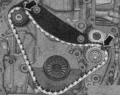
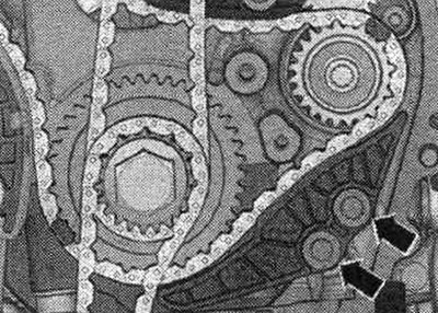
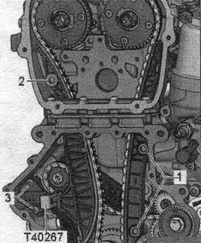
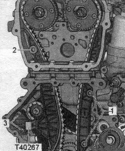
Chain drive
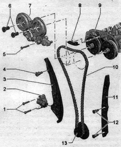
1. Bolt: 9 Nm. 2. Chain tensioner: spring-loaded; before removing, secure with the "T40267" lock. 3. Tension bar for the drive chain. 4. Guide bolt: 20 Nm. 5. Bolt: replace; 4 Nm and turn 180° further. 6. Control valve: left-hand thread; 35 Nm; remove using puller "T10352/2". 7. Crankshaft support ramp. 8. Timing chain guide bar. 9. Camshaft housing. 10. Camshaft chain: Before removing, mark the direction of rotation with paint. 11. Timing chain guide bar. 12. Guide bolt: 20 Nm. 13. Sprocket: crankshaft.
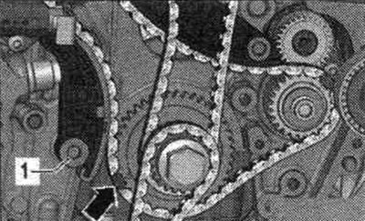
Crankshaft sprocket - mounting position
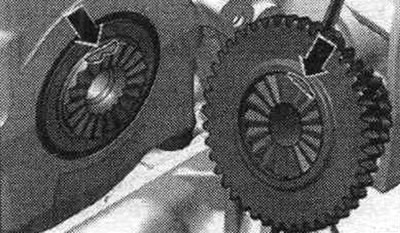
Both surfaces of the "arrow" must be located opposite each other.
Removal and installation the camshaft chain drive
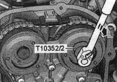
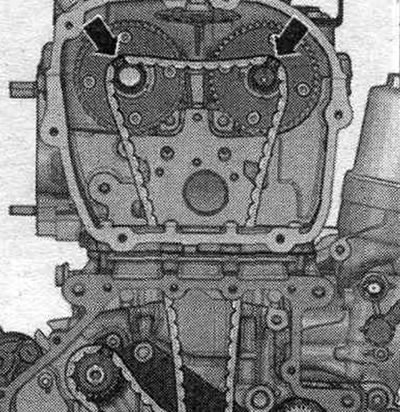
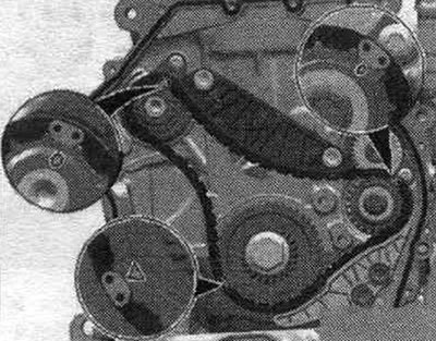
Remove the front support panel. Remove the upper timing chain cover. The control valves have left-hand threads. Remove the control valves using the puller "T10352/2" in the "direction of the arrow".
Unscrew the "arrow" bolts and remove the bearing housing.

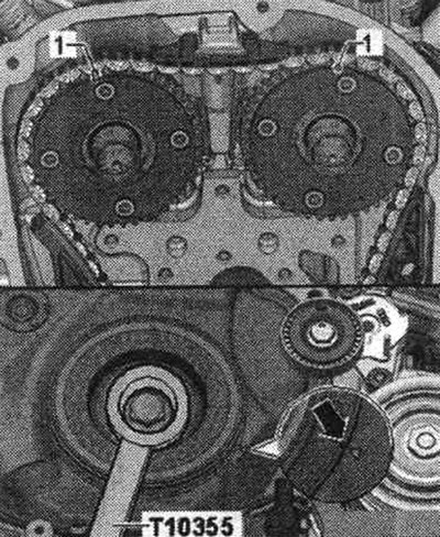
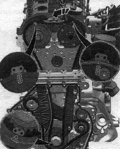
Turn the vibration damper with counter-support "T10355" to the "TDC" position "arrow". The notch on the vibration damper must be opposite the arrow mark on the lower timing chain cover. The "1" marks on the camshafts must face upwards. Remove the lower chain drive cover.
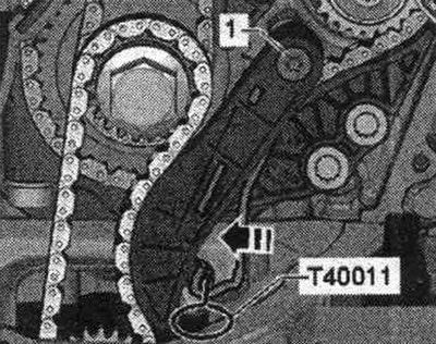
Press down the oil drive chain tensioner. pump in the "direction of the arrow" and lock with the "T40011" lock. Remove the oil chain tensioner. pump "1".
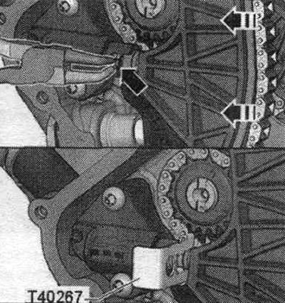
Compress the chain tensioner circlip "arrow". Push the chain tensioner rail in the "direction of the arrow" and lock it with the retainer "T40267". Remove the drive chain from the sprockets and hang it on the camshaft journals. The camshafts rotate in the direction of engine rotation.
Remove the chain drive tension bar "2", Remove the camshaft chain drive damper bar "1".
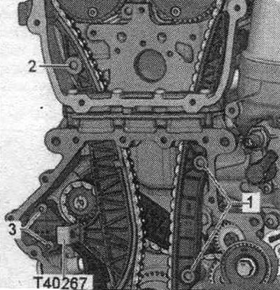
Remove balance shaft drive chain tensioner "1". Remove tensioner bar "2". Remove chain guide "4".
Unscrew the "arrow" bolt of the vibration damper. Remove the gear transmission, to do this remove the oil drive chain. pump. Remove the camshaft drive chain.
Installation
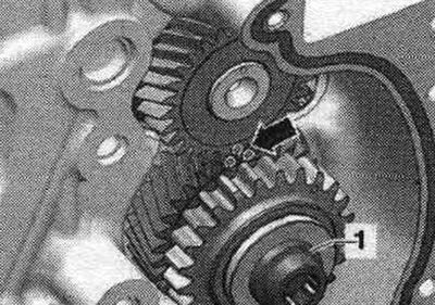
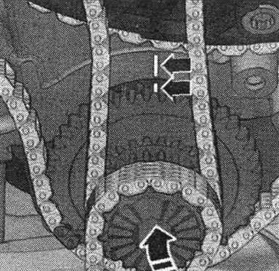
Check the TDC position of the crankshaft: the arrow marks should be opposite each other. Apply a mark "1" to the cylinder block using a permanent marker.
Apply mark "2" to tooth of sprocket "1" using a permanent marker.
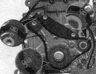
Turn the intermediate gear and balance shaft until the arrow marks align.
The colored links of the balance shaft drive chain must be located opposite the marks on the sprockets. Install the balance shaft drive chain so that the colored chain links "arrows" are located opposite the marks on the sprockets.
Hang the drive chain with the arrow marks on the camshaft journals.
Install the oil drive chain. pump on gears. Move the gears in the "direction of the arrow" towards the engine and secure them on the crankshaft. The arrow marks must match.
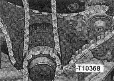
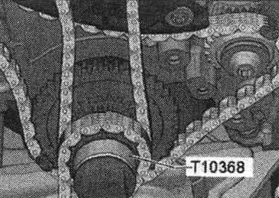
Screw on the T10368 mandrel using the arrow bolt of the torsional vibration damper.
Install the balance shaft drive chain damper and tighten the arrow bolts.
Place the colored link of the balance shaft drive chain "arrow" on the sprocket mark, install the drive chain tensioner and tighten bolt "1".
Install chain tensioner "1" using thread locking compound.

Check the adjustment again: the colored chain links should be positioned on the corresponding marks.
The following tasks must be completed simultaneously. This requires the assistance of a second mechanic. The colored links on the camshaft drive chain should be aligned with the marks on the sprockets. Align the colored links of the camshaft timing chain with the marks on the sprockets. To do this, rotate the camshafts using the "T40266" tool. Align the colored link of the camshaft timing chain with the mark on the sprocket.
Install the timing chain tensioner and tighten bolt "2". Install the camshaft timing chain guide and tighten bolts "1".
Place the bearing housing on the bearing and tighten the "arrow" bolts by hand. Remove the "T40267" locking pin. Tighten the "arrow" bolts of the bearing housing. Install the control valve. Installation in reverse order. Install the lower chain drive cover. Install the upper drive chain cover. Install the tensioner for the poly V-belt. Install the poly V-belt. Install the front support panel. Install the front bumper cover and bumper.
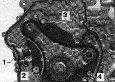
Balance shaft drive chain
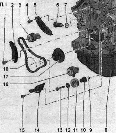
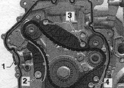
1. Guide bolt: 20 Nm. 2. Tensioner bar: for timing chain. 3. Balance shaft: exhaust side; must be replaced after removal; lubricate the support with oil. 4. Guide bolt: 20 Nm. 5. Idler bar: for timing chain. 6. Chain tensioner: 65 Nm. 7. Lip seal. 8. Cylinder block. 9. Sealing ring: lubricate with oil. 10. Support pin: lubricate with oil. 11. Idler gear: After loosening the bolt, the idler gear must be replaced. 12. Washer. 13. Bolt: replace; after unscrewing the bolt, the intermediate gear must be replaced. 14. Stabilizer bar: for balance shaft drive chain. 15. Guide bolt: 20 Nm. 16. Balance shaft: intake side; must be replaced after removal; lubricate the support with oil. 17. Sprocket. 18. Balance shaft drive chain.
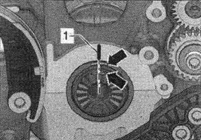
Support pin - mounting position
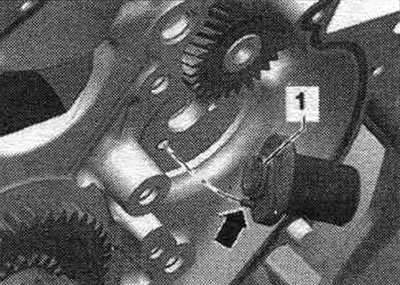
Replace and lubricate the seal. ring "1". The mounting pin "arrow" of the support pin must enter the hole in the cylinder block. Lubricate the support pin.
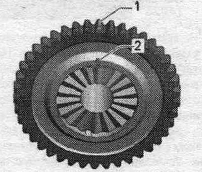
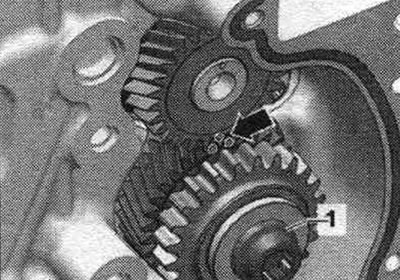
Intermediate gear - sequence, tightening
The intermediate gear needs to be replaced. Otherwise, the tooth profile clearance will not be adjusted, which will lead to engine damage. The new intermediate gear is coated with a varnish that will soon wear off and the tooth backlash will automatically adjust. Tighten the new bolt in the following order.
1. Pre-tighten to 10 Nm.
2. Turn the intermediate gear. The intermediate gear should not have any play, otherwise its fastening should be loosened and tightened again.
3. Tighten to 25 Nm.
4. Tighten 90° further with a regular wrench.
Removal and installation the balance shaft drive chain
Remove the upper timing chain cover. Remove the lower chain drive cover. Remove the camshaft chain drive. Remove the camshaft chain tensioner "3".
Remove balance shaft drive chain tensioner "1". Remove tension bar "2". Remove damper "3". Remove damper "4". Remove balance shaft drive chain.
Installation
Rotate the intermediate gear and balance shaft until the arrow marks align. The colored timing chain links should be installed according to the markings on the sprockets. Install the timing chain, the colored links of the timing chain must be installed according to the markings on the sprockets.
Install the drive chain tensioner and tighten bolts "4". Install the drive chain tensioner and tighten bolts "3". Install the drive chain tensioner bar and tighten bolt "2". Install the chain tensioner "1" using thread locking compound. Check the adjustment again. Check the marks on the intermediate gear and balance shaft "arrow". For clarity, the marks on the intermediate gear and balance shaft are shown with the chain removed. Installation in reverse order. Install the camshaft chain. Install the lower chain drive cover. Install the upper drive chain cover. Install the poly V-belt tensioner. Install the poly V-belt.