



Automatic transmission of car Audi A4 B7

Automatic Transmission — Specifications
Model AT - ZF 6HP-19 ATF type and volume — see Specifications to Chapter 1 Tightening force of threaded connections, Nm Note: Fasteners marked with the sign...
Model AT - ZF 6HP-19 ATF type and volume — see Specifications to Chapter 1 Tightening force of threaded connections, Nm Note: Fasteners marked with the sign...

Automatic transmission (AT) — general information
The AT identification plate is located on the bottom side of the AT (And in illustration 1.1). The purpose of the fields of this plate is described in...
The AT identification plate is located on the bottom side of the AT (And in illustration 1.1). The purpose of the fields of this plate is described in...
Troubleshooting
If you detect a fault with the AT, first of all, check the ATF level ( see Chapter 1 ). If the level is insufficient, check the condition of the corresponding...
If you detect a fault with the AT, first of all, check the ATF level ( see Chapter 1 ). If the level is insufficient, check the condition of the corresponding...

Removal and installation of AT and torque converter
Note: The description is given using 2.0 TFSI AWD models as an example. 1. Turn on the AT mode "N". 2. Disconnect the negative battery cable ( see Chapter 5 )...
Note: The description is given using 2.0 TFSI AWD models as an example. 1. Turn on the AT mode "N". 2. Disconnect the negative battery cable ( see Chapter 5 )...
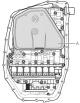
Removal and installation of the oil pan AT
1. Wait until the AT cools down. 2. Unscrew the plug ( 1 in illustration 1.1 ) drain hole and drain the ATF. 3. Remove the 23 oil pan mounting bolts in a...
1. Wait until the AT cools down. 2. Unscrew the plug ( 1 in illustration 1.1 ) drain hole and drain the ATF. 3. Remove the 23 oil pan mounting bolts in a...

Removal and installation of the electrohydraulic unit (mechatronics)
1. Disconnect the negative cable from the battery ( see Chapter 5 ). 2. Remove the ATF oil pick-up ( see Section 4 ). 3. Disconnect the connector (2 in the...
1. Disconnect the negative cable from the battery ( see Chapter 5 ). 2. Remove the ATF oil pick-up ( see Section 4 ). 3. Disconnect the connector (2 in the...

Work with the ATF cooling circuit
1. The details of the ATF cooling circuit on the 2.0 TFSI models are shown in the illustration. 6.1 ATF Cooling Circuit Components 1. Nut, 8 Nm; 2, 9....
1. The details of the ATF cooling circuit on the 2.0 TFSI models are shown in the illustration. 6.1 ATF Cooling Circuit Components 1. Nut, 8 Nm; 2, 9....

Work with the selector lever
1. The selector lever installation details are shown in the illustration. 7.1. Selector lever installation details 1. Selector lever; 2. Lever bushing 1; 3....
1. The selector lever installation details are shown in the illustration. 7.1. Selector lever installation details 1. Selector lever; 2. Lever bushing 1; 3....

Removal and installation the selector mechanism
1. The details of the selector mechanism installation using the example of models with numbers from 8E 002700 are shown in the illustration. 8.1. Selector...
1. The details of the selector mechanism installation using the example of models with numbers from 8E 002700 are shown in the illustration. 8.1. Selector...

Removal, installation and adjusting the selector cable
1. The details of installing the selector cable using the example of models with a number from 8E 002700 are shown in the illustration. The description of...
1. The details of installing the selector cable using the example of models with a number from 8E 002700 are shown in the illustration. The description of...

Removal, installation and adjusting the locking cable
1. The details of installing the locking cable using the example of models with numbers from 8E 002700 are shown in the illustration 9.1 . Removal and...
1. The details of installing the locking cable using the example of models with numbers from 8E 002700 are shown in the illustration 9.1 . Removal and...

Continuously Variable Transmission (CVT) — General Information
The identification data for the CVT is located on its underside (see illustration 11.1), and also on the vehicle data stickers ( see Introduction ). The first...
The identification data for the CVT is located on its underside (see illustration 11.1), and also on the vehicle data stickers ( see Introduction ). The first...

Removal and installation of CVT
Note: The description is given using 2.0 TFSI models as an example. 1. Set the selector lever to position "P". 2. Disconnect the negative cable from the...
Note: The description is given using 2.0 TFSI models as an example. 1. Set the selector lever to position "P". 2. Disconnect the negative cable from the...
This section is available on russian, bulgarian, belarusian, ukrainian, serbian, croatian, romanian, polish, slovak, hungarian
Similar sections of other Audi car models:
Transmission: Automatic transmission Audi 80 B3 (1986-1991, petrol)
Transmission: Automatic transmission Audi 100 C3 (1982-1990)
Transmission: Automatic transmission Audi A3 Type 8L (1996-2003)
Transmission: Automatic transmission Audi A6 C4 (1994-1997)
Transmission: Automatic gearbox Audi Q7 Typ 4L (2005-2015, diesel)
Transmission: Automatic transmission Audi 80 B3 (1986-1991, petrol)
Transmission: Automatic transmission Audi 100 C3 (1982-1990)
Transmission: Automatic transmission Audi A3 Type 8L (1996-2003)
Transmission: Automatic transmission Audi A6 C4 (1994-1997)
Transmission: Automatic gearbox Audi Q7 Typ 4L (2005-2015, diesel)
Share information:
- General information
- Operating instructions
- Power unit
- Petrol engines 1.8 l
- Petrol engines 1.8/2.0 l
- Petrol engines 3.0 l
- Petrol engines 3.2 l
- Fuel system (petrol)
- Diesel engines 2.0 l (CA*)
- Diesel engines 2.0 l (CJCB)
- Diesel engines 2.7/3.0 l
- Diesel engines 3.0 l
- Fuel system (diesel)
- Transmission
- Manual gearbox 0B1
- Manual gearbox 0B2
- Manual gearbox 0B3
- Manual gearbox 0B4
- Automatic transmission 0B5
- Automatic transmission 0B6
- Automatic transmission 0AW
- All-wheel drive system
- Chassis
- Front suspension
- Rear suspension
- Brake system
- Steering system
- Body
- Exterior
- Interior
- Seats
- Doors, locks and windows
- Security system
- Heating and air conditioning
- Electrical equipment
- Audio system
- Power devices
- Equipment and devices
- Lighting and lamps
- Electrical circuits
- General information
- Introduction to manual
- Troubleshooting
- Operating instructions
- Maintenance
- Power unit
- Petrol engines 2.0 (ALT)
- Petrol engines 2.0 (TFSI)
- Petrol engines 1.8 (MPI)
- Diesel engines
- Cooling system
- Air conditioner
- Fuel and exhaust system
- Ignition system
- Starting and charging
- Transmission
- Clutch
- Manual gearbox
- Automatic gearbox
- Drive shafts
- Chassis
- Brake system
- Front suspension
- Rear suspension
- Steering
- Body
- Exterior
- Interior
- Electrical equipment
- Equipment and devices
- Lighting and signaling
- Windscreen wipers and washers
- Electrical diagrams
- Electrical diagrams (since 2007)
- General information
- Vehicle Description
- User manual
- Maintenance
- Power unit
- Gasoline engine
- Diesel engine
- Lubrication system
- Cooling system
- Supply system
- Injection system
- Exhaust system
- Ignition and control
- Transmission
- Gear box
- Clutch and drive shafts
- Chassis
- Brake system
- Car suspension
- Steering
- Body
- Heating and ventilation
- Exterior (external elements)
- Interior (internal elements)
- Electrical equipment
- Power devices
- Lighting and appliances
- Electrical circuits
- General information
- Introduction to the guide
- Car care
- Power unit
- Engine repair
- Lubrication system
- Cooling system
- Injection and control system
- Ignition system
- Power and exhaust system
- Transmission
- Clutch and drive shafts
- Car gearbox
- Chassis
- Suspension and wheels
- Steering
- Brake system
- Body
- Interior
- Exterior
- Electrical equipment
- Equipment and devices
- Lighting and signaling
- Power devices
- Electrical circuits
- General information
- Introduction to the guide
- Car care
- Maintenance (gasoline)
- Maintenance (diesel)
- Power unit
- Gasoline engines
- Diesel engines
- Engine overhaul
- Cooling system
- Fuel injection (gasoline)
- Fuel system (diesel)
- Exhaust system
- Ignition system
- Transmission
- Clutch
- Mechanical gearbox
- Automatic gearbox
- Drive shafts
- Chassis
- Brake system
- Car suspension
- Steering
- Body
- Exterior
- Interior
- Doors, locks and windows
- Heating and ventilation
- Electrical equipment
- Power devices
- Equipment and devices
- Electrical circuits
- General information
- Vehicle description
- Maintenance
- Power unit
- Engine repair
- Turbocharging
- Exhaust system
- Cooling system
- Ignition system
- Fuel system
- Motronic injection system
- MPI and MPFI injection system
- Transmission
- Clutch
- Gearbox and shafts
- Chassis
- Steering
- Car suspension
- Brake system
- Wheels and tires
- Body
- Heating and ventilation
- Body parts
- Electrical equipment
- Fuses and relays
- Power devices
- Lighting and lamps
- Tools and devices
- Electrical circuits