
Table of contents: Removal and installation ↓ Checking and adjusting ↓ Setting the selector cable to its… ↓
1. The details of installing the selector cable using the example of models with a number from 8E 002700 are shown in the illustration. The description of removing and installing the selector cable is presented using the example of 2.0 TFSI models.
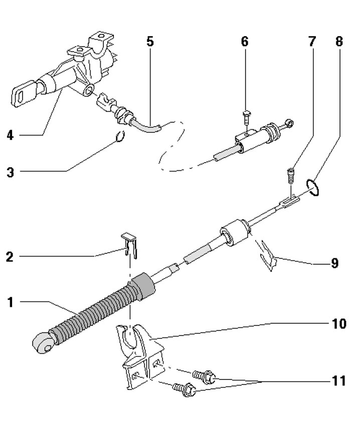
9.1. Selector cable installation details 1. Selector cable; 2. Cable retainer 1 on bracket 9, subject to replacement; 3. Cable retainer 5; 4. Ignition switch; 5. Ignition key removal lock cable; 6. Cable adjustment bolt 5.8 Nm; 7. Cable clamp bolt 1, 13 Nm; 8. Cable sealing ring 1, subject to replacement; 9. Cable support bracket 1; 10. Bolt, 8 Nm
Removal and installation
2. Remove the selector cover (see Section 7) and set the selector lever to position "D".
3. Insert key T40031 (see illustration 8.6) through the hole in the selector mechanism and loosen the clamp bolt on the back of the selector lever by about 1 turn. Leave the key in the hole.
4. Release the fasteners (2 and 3 in Illustration 5.5 Chapter 2).
5. Press the hinge socket (1 in illustration 3.14) selector cable from the selector shaft lever. Mark the position of the selector cable bracket, unscrew the bolts (arrows) and remove the bracket. Move the selector cable aside.
6. Remove the heat shield of the propeller shaft (see illustration 3.13).
7. Remove the heat shield (1 in the illustration) exhaust system under the selector mechanism, unscrew the bolts securing the propeller shaft to the AT (see Chapter 8) and press the shaft (2) back. Tie the cardan shaft to the body to the side.
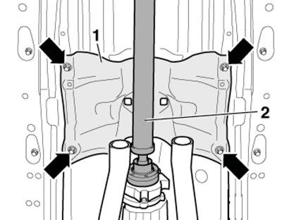
9.7. Heat shield under the selector mechanism
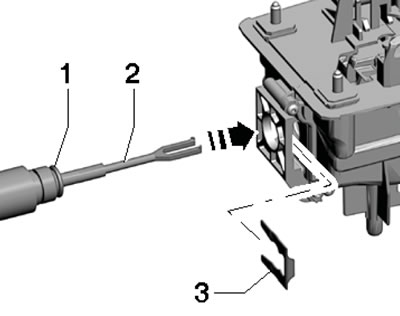
8. Pull out the lock (1 in illustration 8.9) selector cable to the side and pull the cable (2) out of the selector mechanism. Do not bend the cable.
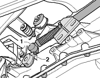
9. Installation is performed in the reverse order of dismantling the components. When connecting the cable joint socket, the selector lever on the AT must be in the "D" position. Use a new sealing ring (1 in the illustration) on the selector cable and insert the cable into the selector mechanism (arrow). Use a new lock (3). Before installing the propeller shaft, adjust the cable as described in the subsection below.
9.9. Sealing ring (1) and retainer (3) of the selector cable
Checking and adjusting
10. Remove the selector cover (see Section 7) and set the selector lever to position "D".
11. Insert key T40031 (see illustration 8.6) through the hole in the selector mechanism and loosen the clamp bolt on the back of the selector lever by about 1 turn. Leave the key in the hole.
12. Carefully move the selector cable forward and backward without moving the selector lever. Then move the selector to the manual shift position and do not touch it again during the adjustment process.
13. Tighten the clamp bolt and install the selector cover. Check the selector for proper operation - if it is not, return the cable to its initial position as described in the subsection below.
Setting the selector cable to its initial position
14. Remove the selector cover (see Section 7) and set the selector lever to position "D".
15. Make sure the cable clamp bolt is tightened and move the selector lever to the "P" position.
16. Remove the bolts (arrows in illustration 3.14) and remove the bracket.
17. Press the selector shaft lever (2 in the illustration) in the rear direction until it stops, so that the "P" position lock is engaged (it is impossible to turn the front wheels).
9.17. Selector shaft lever (2) and hinge socket (1)
Make sure that the selector cable (1) is not bent, twisted or stressed.
18. Secure the bracket (see illustration 3.14) and adjust the cable as described in the subsection above.