
Note: The description is given using 2.0 TFSI models as an example.
1. Set the selector lever to position "P".
2. Disconnect the negative cable from the battery (see Section 5).
3. Remove the decorative engine cover.
4. Follow the steps described in paragraphs 5-9 Section 3.
5. Remove the inner covers on the bottom of the car (see illustration).
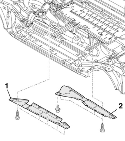
12.5. Covers on the bottom of the car
6. Remove the center tunnel cross members (see illustration 8.7).
7. Loosen the clamp (see illustration 17.3 Chapter 4) and pull back the exhaust pipe.
Note: Do not bend the flexible section of the exhaust system more than 10°. Remove the heat-insulating screen on the exhaust pipe.
8. Support the crossmember with a transmission jack, placing a wooden block between them (see illustration).
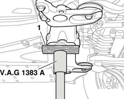
12.8. Jack under the crossbar
9. Unscrew the bolts one by one (1-4 in the illustration) and slowly lower the crossbar on the jack.
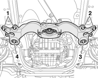
12.9. External fastening of the crossbar
10. Give the nuts (see illustration) and remove the cross member.
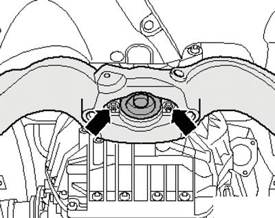
12.10. Internal fastening of the crossbar
11. Remove the thermal insulation of the right drive shaft (see illustration 5.43 Chapter 2). Separate both drive shafts from the CVT (see chapter 8).
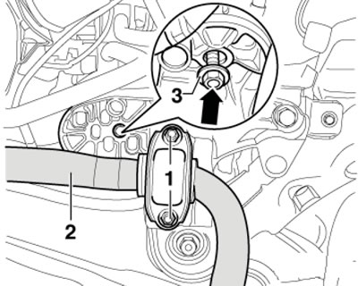
12. Remove the bolts (arrows in illustration 17.37 Chapter 2) fastening the exhaust pipe to the catalytic converter. Loosen the nut (1) on the bracket and remove the exhaust pipe.
13. Give the nuts (1 and 2 in the illustration) and disconnect the ATF tubes. Unscrew the fasteners (arrows) of the tube brackets.
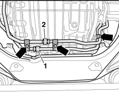
12.13. Fastening ATF tubes
14. Unscrew the ATF filter fastener (see illustration).
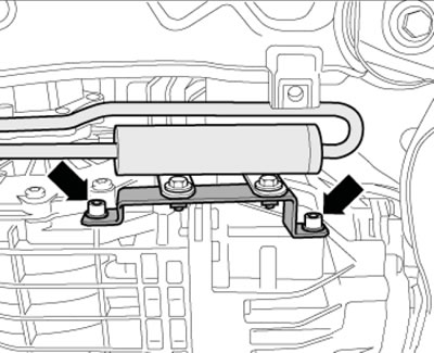
12.14. ATF filter fastening
15. Give the nuts (1 and 2 in Illustration 29.8 Chapter 2) and disconnect the ATF pipes, unscrew the fasteners (arrows) of the pipe bracket.
16. Unscrew the bolt (see illustration 5.45 Chapter 2) and separate the ATF pipe from the CVT. Remove the ATF pipes.
17. Disconnect the connector (1 in the illustration), release the wiring harness from the holders (arrows) and move it to the side.
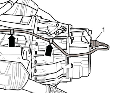
12.17. CVT Wiring Harness
18. Remove the bolts (2 in the illustration) and remove the bracket (3) of the selector cable.
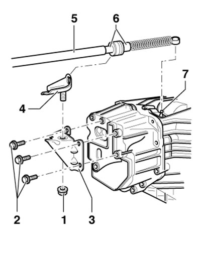
12.18. Fastening the selector cable bracket
19. Using the 80-200 tool, pry up and separate the selector cable (And in the illustration) from the selector shaft.
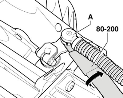
12.19. Separating the selector cable from the CVT
20. Remove the bolts (2 in the illustration) and from the CVT its support (1).
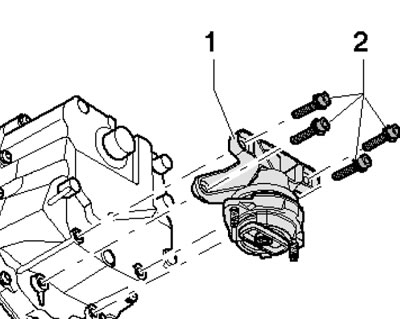
12.20. Removing the CVT support
21. Remove the bolts (1-5 and 11 in Illustration 5.64a of Chapter 2). Loosen the bolt (6) and leave it screwed in by hand.
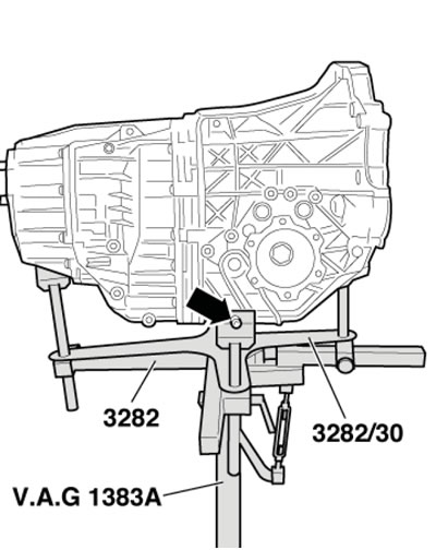
22. Secure the CVT to the transmission jack using suitable adapters and a support plate (see illustration). Raise the CVT slightly with a jack.
12.22. Fixing the CVT on a jack
23. Remove the bolts (arrows in illustration 27.30 Chapter 2) and remove the jet support.
24. Give me the nuts (1 in the illustration) on the left and right sides and tilt the anti-roll bar (2) downwards. Loosen the nuts (3) on the left and right engine mounts until the bottom of the nut is flush with the bottom edge of the stud. Raise the engine on tool 10-222A (see illustration 2.4 Chapter 6) so that both nuts (3) touch the bottom of the console.
12.24. Fasteners (1) of the anti-roll bar (2) and engine mount (3)
25. Remove the bolts (1 in illustration 5.64a Chapter 2), tie up the drive shafts, unscrew the remaining bolt securing the CVT to the engine and separate them from each other. Lower the CVT on the jack.
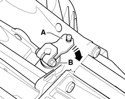
26. Jack up the CVT enough to allow the selector cable to be installed. Press the selector shaft lever (And in the illustration) backwards until it stops (arrow) to engage the "P" position lock.
12.26. Fixing the CVT in the "P" position
27. Carefully fix (press) the clip (2 in the illustration) selector cable joint on the selector shaft lever. Do not allow the cable to bend or twist. If necessary, support the lever, otherwise further adjustment of the cable may not be carried out accurately enough.
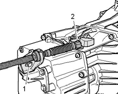
12.27. Selector cable connection
28. If the bracket (3 in illustration 12.18) the selector cable has been removed from the CVT, insert the bolts (2) into the bracket (3) and secure it with bolts to a torque of 23 Nm.
29. Install the bracket (1 in illustration 12.27) in accordance with the marking.
30. Further installation is carried out in the reverse order of dismantling the components. After installation, adjust the ATF level (see chapter 1) and adjust the selector cable (see Section 9).
[The article is a reprint of material from: AUDImanual]