
Note: To remove the exhaust system assembly, please have an assistant assist you due to its considerable weight. Wait until the exhaust system has cooled down before removing.
Note: The procedure is described for the most common models. The steps are similar for other models.
2.0 TFSI engines
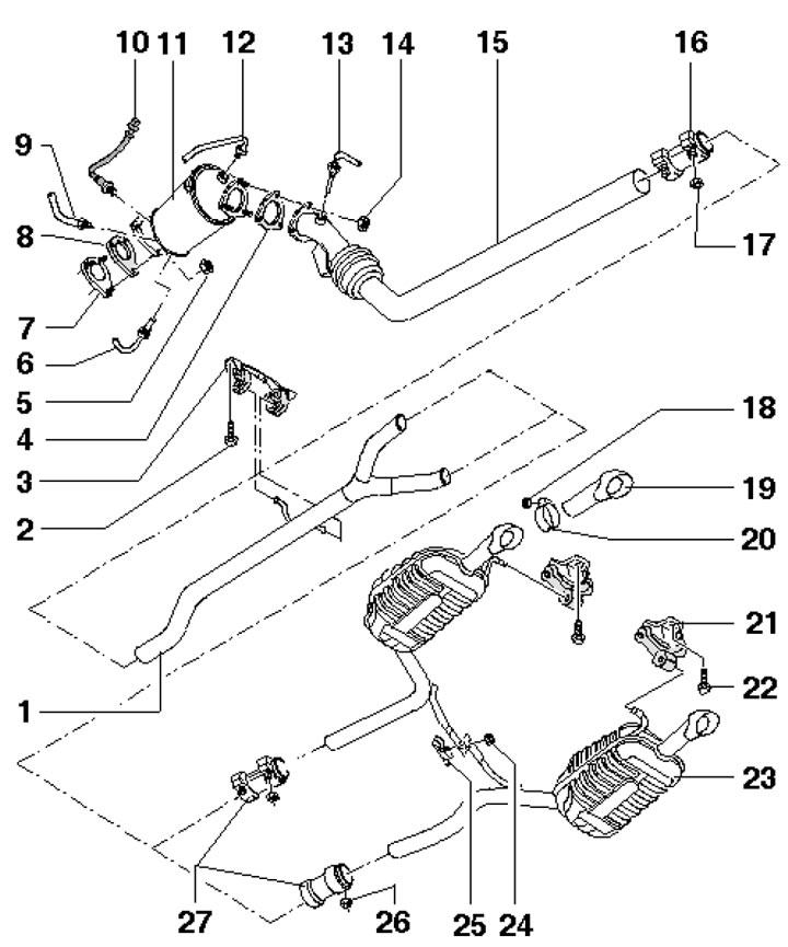
1. The exhaust system installation details are shown in the illustration.
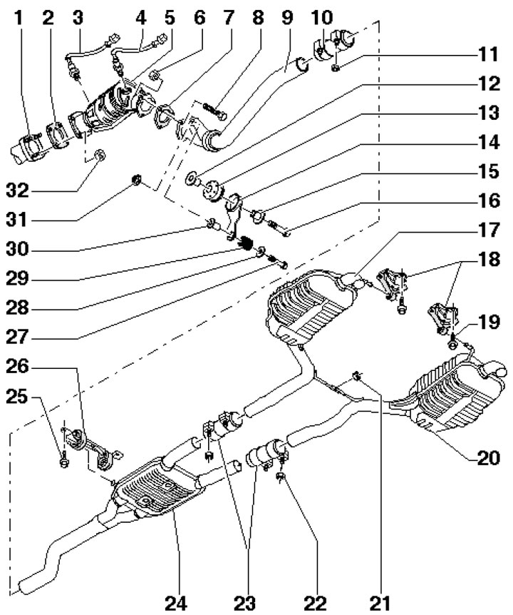
17.1. Exhaust system installation details. 1. Turbocharger; 2, 7. Gasket, subject to replacement; 3. Pre-catalytic lambda probe, 55 Nm; 4. Post-catalytic lambda probe, 55 Nm; 5. Catalytic converter; 6. Nut, 25 Nm, subject to replacement; 8. Bolt; 9. Front exhaust pipe with flexible section (do not bend more than 10°); 10. Clamp; 11. Nut, 23 Nm, subject to replacement; 12, 15. Spacer sleeve; 13. Buffer; 14. Bracket; 16. Bolt; 17. Rear left muffler; 18. Rubber hangers; 19, 25. Bolt, 23 Nm; 20. Rear right muffler; 21, 22. Nuts, 23 Nm; 23. Clamps for separate replacement of the central and rear mufflers; 24. Central muffler; 26. Rubber suspension; 27. Bolt; 28. Washer; 29. Compressible ring; 30. Spacer sleeve; 31. Nut, 25 Nm, subject to replacement; 32. Nut, 30 Nm, subject to replacement
2. The central and rear mufflers are installed as a non-separable part. To replace a separate muffler, remove the muffler assembly, cut the pipe in front of the muffler and connect the new muffler using a clamp.
Front exhaust pipe
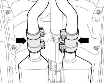
3. Loosen the clamps and push the coupling back (see illustration).
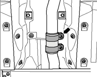
17.3. Clamps
4. Remove the bolts securing the front exhaust pipe to the catalytic converter (arrows in illustration 17.37 Chapter 2), unscrew the bolt (1) on the bracket and remove the front exhaust pipe.
5. Installation is performed in the reverse order of dismantling the components. Use new fasteners.
Catalytic converter
6. Remove the upper decorative engine cover (see Chapter 2)
7. Loosen the fasteners of the expansion tank of the cooling system and put the tank aside without disconnecting the hoses from it (see Chapter 3).
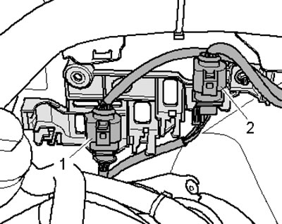
8. Disconnect the post-catalytic converter connectors (1 in illustration 17.24 Chapter 2) and pre-catalytic (2) lambda probes, move the wiring to the side.
9. Remove the front exhaust pipe (see subsection above).
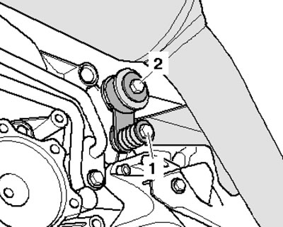
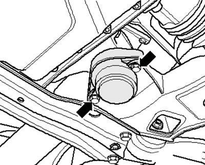
10. From under the vehicle, remove the catalytic converter mounting nut shown in the illustration to the turbocharger assembly.
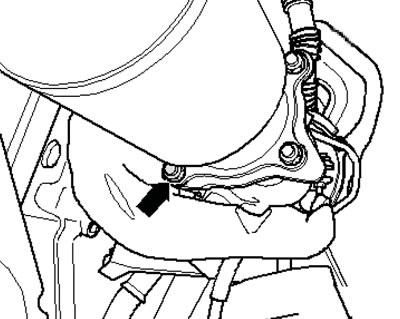
17.10. Lower nut for fastening the catalytic converter
11. Remove the remaining three nuts from the engine compartment side and remove the catalytic converter by moving it upwards.
12. Installation is carried out in the reverse order of dismantling the components.
Engines 3.2 FSI
13. The exhaust system installation details are shown in the illustration using FWD models as an example.
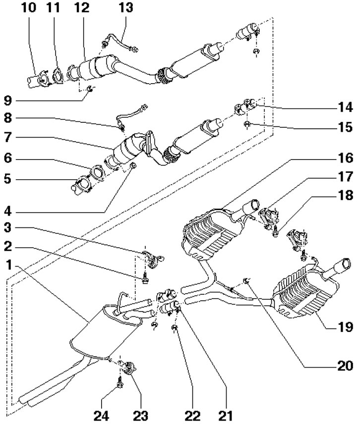
17.13. Exhaust system installation details 1. Central muffler; 2. Bolt, 23 Nm; 3. Support; 4. Nut, 27 Nm, subject to replacement; 5/10. Exhaust manifold of cylinder block No.1/2; 6, 11. Gasket, subject to replacement; 7/12. Front exhaust pipe with catalytic converter and front muffler (cylinder block #1/2); 8/13. Post-catalytic lambda probe (cylinder block No.1/2); 9. Nut, 27 Nm, subject to replacement; 14. Front clamps; 15. Nut, 23 Nm; 16/19. Rear muffler with outlet pipe (left/right side); 17. Suspension; 18. Bolt; 20. Nut, 23 Nm, subject to replacement; 21. Rear clamps; 22. Nut, 23 Nm; 23. Suspension; 24. Bolt, 23 Nm
14. The central and rear mufflers are installed as a non-separable part. To replace a separate muffler, remove the muffler assembly, cut the pipe in front of the muffler and connect the new muffler using a clamp.
15. The following describes the removal and installation of the front exhaust pipe assembly with the catalytic converter using the left side of CVT models as an example.
16. Remove the upper decorative engine cover (see Chapter 2)
17. Loosen the fasteners of the expansion tank of the cooling system and put the tank aside without disconnecting the hoses from it (see chapter 3).
18. Disconnect the connector (1 in the illustration) post-catalytic lambda probe No.2 and move the wiring to the side.
17.18. Left side lambda probe wiring connector
19. Remove the nut from above (2 in the illustration) fastening the exhaust pipe to the exhaust manifold.
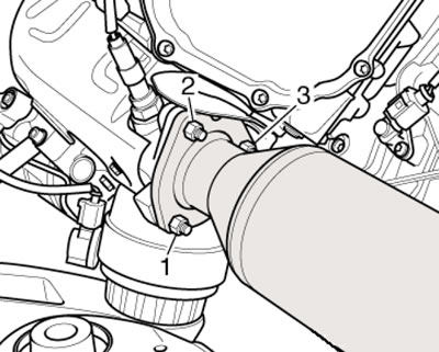
17.19. Exhaust pipe mounting nuts
20. Remove the front left wheel.
21. On models with independent/additional heating, unscrew the bolts (arrows in illustration 5.4 Chapter 2) its exhaust pipe from the soundproofing screen.
22. Release the fasteners (1 and 2 in Illustration 5.5 Chapter 2) and remove the front sound insulation. If there is rear sound insulation, release the clips (3) and remove it.
23. Remove the bolts (arrows in the illustration) left drive shaft mounts and separate it from the transmission. Remove the remaining nuts from underneath the car (1 and 3 in illustration 17.19) front exhaust pipe mounts.

17.23. Fastening the left drive shaft to the transmission
24. Remove the bolts (1 in the illustration) and remove the front exhaust pipe bracket.
17.24. Fastening the front exhaust pipe bracket
25. Loosen the clamps and disconnect the exhaust pipes (see illustration).
17.25. Front clamps
26. Remove the bolt securing the left and right transmission supports (see illustration).
17.26. Fastening of transmission supports
27. Support the transmission as shown in the illustration.
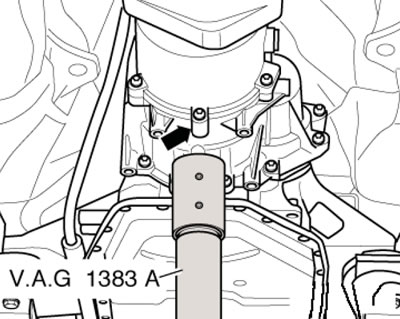
17.27. Supporting the transmission
28. Remove the heat shield of the left transmission support, unscrew the bolts (see illustration) left support mounts, support the transmission until it stops against the center tunnel and guide the front exhaust pipe down between the transmission and the subframe, rotating it if necessary.
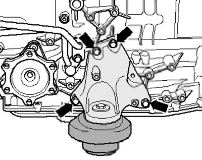
17.28. Removing the transmission support
29. Installation is carried out in the reverse order of dismantling the components.
Diesel engines 2.0L DOHC
30. Details of the exhaust system installation using the example of AWD models with a particulate filter are shown in the illustration.
17.30. Exhaust system installation details 1. Y-section; 2. Bolt, 25 Nm; 3. Support; 4, 8. Gasket, subject to replacement; 5. Nut, 27 Nm; 6. Exhaust gas temperature sensor before diesel particulate filter, 45 Nm; 7. Turbocharger; 9, 12. Pressure line, 30 Nm; 10. Lambda probe, 55 Nm; 11. Diesel particulate filter; 13. Exhaust gas temperature sensor behind the diesel particulate filter, 45 Nm; 14. Nut, 23 Nm, subject to replacement; 15. Front section with flexible section; 16. Front clamp; 17/18. Nut, 23/25 Nm; 19. Exhaust pipe; 20. Clamp; 21. Suspension; 22. Bolt, 23 Nm; 23. Rear muffler; 24, 26. Nut, 23 Nm; 25. Connecting bracket; 27. Rear clamps
[Text provided by the online resource: AUDIMANUAL]