Repair Chevrolet Repair Toyota Repair Honda Repair AvtoVAZ Repair Mercedes-Benz Repair BMW Repair Opel
Home  |  Contacts  |  Sitemap  |    
English Русский
Български
Беларускі
Український
Српски
Hrvatski
Română
Polski
Slovenský
Magyar
AudiManual.ru


  • AUDI 80
  • AUDI 100
  • AUDI A3
  • AUDI A4
  • AUDI A6
  • AUDI A8
  • AUDI Q
  • OTHER
  • ARTICLES
C4 (1990-1994) C4 (1990-1994, petrol) C3 (1982-1990) C3 (1982-1990, petrol) C3 (1982-1990, diesel)

Exhaust system — general description and replacement of components (Audi 100 C3)

  • Home
  • Audi 100
  • C3 (1982-1990, diesel)
  • Power unit
  • Exhaust system
  • Exhaust system — general description and replacement of components
            0
Table of contents: General description ↓ Removal ↓

General description


1. The exhaust system consists of a front outlet pipe, an intermediate pipe with a muffler, and an exhaust pipe with a muffler.

2. The system is secured along its entire length to rubber suspensions, which are attached to the bottom of the car with metal brackets.

Removal


3. Each part of the exhaust system can be removed separately. First, jack up the front or rear of the car and place it on axle stands. Alternatively, place the car on an inspection pit or overpass.

Discharge pipe


4. Remove the lower skid plate from under the engine compartment.

5. Where applicable, remove bolts and crossmember from under rear of transmission.

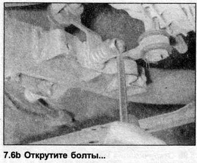
6. Remove the bolts and springs and stops from the mountings at the rear of the exhaust pipe. Note the location of the various components to aid in reassembly (see illustrations).

6. Remove the bolts and springs and stops from the mountings at the rear of the exhaust pipe. Note…


6. Remove the bolts and springs and stops from the mountings at the rear of the exhaust pipe. Note…


6. Remove the bolts and springs and stops from the mountings at the rear of the exhaust pipe. Note…


7. Unscrew the nuts and disconnect the exhaust outlet pipe from the exhaust manifold.


8. Support the intermediate part with a jack or a wooden block.

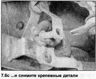
9. Remove the bolts and separate the exhaust outlet pipe from the intermediate part. Remove the O-ring seal and remove the outlet pipe from under the car (see illustrations). Intermediate pipe

9. Remove the bolts and separate the exhaust outlet pipe from the intermediate part. Remove the…


9. Remove the bolts and separate the exhaust outlet pipe from the intermediate part. Remove the…


10. Loosen the clamp bolts and slide the sleeve off the front of the pipe.

11. Unscrew the clamp bolts and disconnect the intermediate pipe from the exhaust pipe and muffler. Remove the ring.

Note: Do not throw the ring, it is sensitive to impacts.


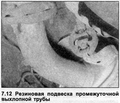
12. Release the rubber hangers and remove the intermediate pipe from under the car (see illustration).

12. Release the rubber hangers and remove the intermediate pipe from under the car (see…


Exhaust pipe with muffler


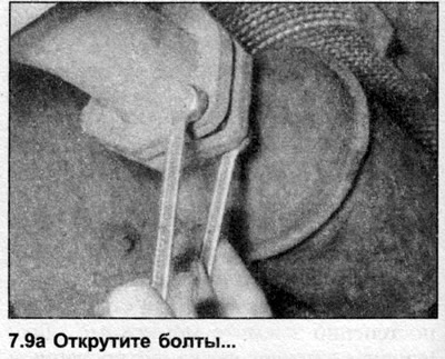
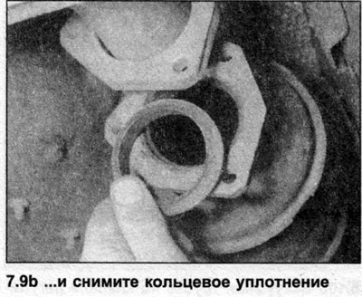
13. Unscrew the clamp bolts and disconnect the intermediate pipe from the exhaust pipe and muffler. Remove the ring.


Note: Do not throw the ring, it is sensitive to impacts.


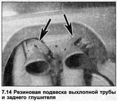
14. Release the rubber mounts and remove the exhaust pipe and muffler from under the car (see illustration). Thermal insulation shields

14. Release the rubber mounts and remove the exhaust pipe and muffler from under the car (see…


15. The heat shields are attached to the underbody with screws. Each shield can only be removed after the corresponding part of the exhaust system has been removed. If the shield is removed to gain access to a component mounted behind it, in some cases it is enough to unscrew the screws and simply lower the shield without disturbing the exhaust system.

Installation


16. Each part is installed in the reverse order of removal, paying attention to the following.
  • a) Ensure that all traces of corrosion are removed from the flange/tube ends and replace all necessary gaskets and O-rings.
  • b) Inspect the rubber mounts for damage or contamination and replace as necessary.
  • c) Apply a special paste for exhaust system joints to the connections formed by the clamping rings to ensure a tight seal. Tighten the clamping ring nuts evenly to the tightening torque specified in the Specifications so that the gap between the clamp halves on both sides is the same.
  • d) Before tightening the exhaust system fasteners, check that all rubber mounts are correctly installed and that there is clearance between the underbody of the vehicle and the exhaust system.
The article was checked by auto expert Nikita Rudakov
This article is available at russian, bulgarian, belarusian, ukrainian, serbian, croatian, romanian, polish, slovak, hungarian

Share information:
Previous articles
Audi 100 C3: Exhaust system
Next articles

Air cooler (intercooler) — removal and installation
Turbogenerator — general description, removal and installation
Exhaust manifold — removal and installation
Exhaust Gas Recirculation System — Information and Component…
Catalytic Converter — General Description and Precautions


Similar articles on other Audi car models:
General description of the cooling system Audi 80 B3 (1986-1991, petrol)
Ignition system — general description Audi A3 Type 8L (1996-2003)
Exhaust system — replacement of components Audi A4 B5 (1994-2001)
General description of the anti-lock braking system (ABS) Audi A6 C4 (1994-1997)
General information about the exhaust system Audi A8 D2 (1994-2002)
Parts and components of the exhaust gas recirculation system Audi Q5 Type 8R (2008-2017)
Exhaust Gas Recirculation System — Design Description Audi A2 (1999-2005)
Link to this page in different formats


Visitor comments

No comments yet


How much will 39 + 33 =


100(C4, 1990-1994) 
  • General information
  • User manual
  • Power unit
  • Engine repair
  • Ignition system
  • Fuel system (gasoline)
  • Fuel system (diesel)
  • Lubrication system
  • Cooling system
  • Exhaust system
  • Transmission
  • Clutch
  • Car gearbox
  • Drive shafts
  • Chassis
  • Car suspension
  • Steering
  • Wheels and tires
  • Brake system
  • Body
  • Ventilation and heating
  • Body repair
  • Electrical equipment
  • Power devices
  • Lighting and appliances
  • Electrical circuits
 
100(C4, 1990-1994, petrol) 
  • General information
  • Operation and maintenance
  • Power unit
  • Engine repair
  • Exhaust system
  • Cooling system
  • Supply system
  • Air filter
  • Mono-Motronic injection system
  • Digifant injection system
  • KE-III-Jetronic and KE-Motronic
  • MPI and MPFI injection system
  • Transmission
  • Clutch
  • Car gearbox
  • Chassis
  • Suspension and steering
  • Brake system
  • Wheels and tires
  • Body
  • Exterior
  • Interior
  • Electrical equipment
  • Fuses and relays
  • Power devices
  • Ignition system
  • Lighting and signaling
  • Equipment and devices
  • Electrical circuits
 
100(C3, 1982-1990) 
  • General information
  • User manual
  • Maintenance
  • Specifications
  • Power unit
  • Engines 4-cylinder
  • Engines 5-cylinder
  • Diesel engine
  • Cooling system
  • Power system (carburetor)
  • Power system (injector)
  • Fuel system (diesel)
  • Transistor ignition system
  • Electronic ignition system
  • Transmission
  • Clutch
  • 4 speed gearbox 014
  • 5 speed gearbox 013 and 093
  • 5 speed gearbox 016 and 012
  • Shift mechanism KP 016
  • Automatic transmission
  • Front wheel drive
  • Chassis
  • Front suspension
  • Rear suspension
  • Steering
  • Brake system
  • Body
  • Body elements
  • Electrical equipment
  • Lighting and appliances
  • Power devices
  • Electrical circuits
 
100(C3, 1982-1990, petrol) 
  • General information
  • Maintenance and operation
  • 4 cylinder engine
  • Engine repair
  • Cooling and lubrication system
  • Supply system
  • Ignition system
  • 5 cylinder engine
  • Engine repair
  • Cooling and lubrication system
  • Supply system
  • Ignition system
  • Transmission
  • Clutch and drive shafts
  • 4 speed gearbox 014
  • 5 speed gearbox 013 and 093
  • 5 speed gearbox 016 and 012
  • Automatic gearbox
  • Chassis
  • Steering
  • Front suspension
  • Rear suspension
  • Brake system
  • Body
  • Body elements
  • Doors, locks and windows
  • Body repair
  • Electrical equipment
  • Equipment and devices
  • Power devices
  • Electrical circuits
 
100(C3, 1982-1990, diesel) 
  • General information
  • User manual
  • Maintenance
  • Troubleshooting
  • Power unit
  • Engine in a car
  • Engine removed
  • Cooling system
  • Fuel system
  • Exhaust system
  • Starting and charging
  • Preheating
  • Transmission
  • Clutch
  • Mechanical gearbox
  • Automatic gearbox
  • Drive shafts
  • Chassis
  • Brake system
  • Suspension
  • Steering
  • Body
  • Exterior
  • Interior
  • Electrical equipment
  • Equipment and devices
  • Electrical circuits
 
AudiManual.ru © 2017-2026 · Mobile version · Feedback · Sitemap: EN BG BY UA RS HR RO PL SK HU · Site search · News and articles
80 B2 · 80 B3 petrol · 80 B3 · 80 B4 · 100 C3 diesel · 100 C3 petrol · 100 C3 · 100 C4 petrol · 100 C4 · A3 Type 8L · A4 B5 petrol · A4 B5 · A4 B6 petrol · A4 B6 · A4 B7 · A4 B8 · A6 C4 · A6 C5 · A6 C5 Allroad · A8 D2 · Q5 Type 8R · Q7 Typ 4L · Audi A2 ·
This site uses cookies 🍪. Click the button to accept this fact.