
Table of contents: Removal ↓ Intake pipe ↓ Catalytic converter (engines ADP,… ↓ Catalytic converter (aEB, AJL… ↓ Short pipe (engines 1Z, AHU, ANN,… ↓ Middle part and muffler ↓ Rear part with muffler ↓ Installation ↓
Warning! Allow the exhaust system to cool down before starting work. The catalytic converter, in particular, operates at very high temperatures. If it is not possible to cool the system, at least put on heat-protective gloves.
Removal
1. Each section of the system can be removed separately. However, the entire system cannot be removed as it passes over the rear beam.
2. To remove part of the system, raise the front of the vehicle and install safety supports. Alternatively, place the vehicle on a ramp, inspection pit or lift.
Intake pipe
(with catalytic converter on AHL petrol engines and all diesel engines)
Note: The flexible braided section of the intake pipe requires careful handling and should not be excessively kinked.
3. Working underneath the vehicle, remove the floor cross member from the body.
4. Remove the air filter assembly as described in Chapter 4A or 4B.
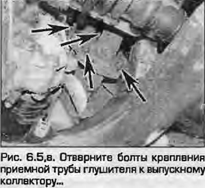
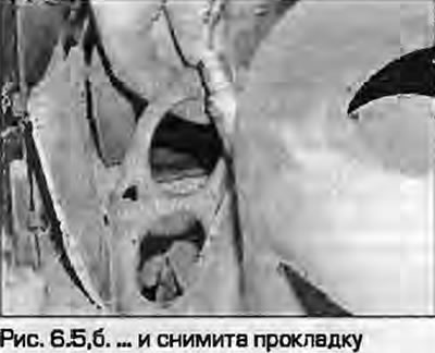
5. Unscrew the nuts and disconnect the intake pipe from the exhaust manifold (catalytic converter on AEB and AJL engines). Remove the gasket (fig. 6.5, a, b).
 |
 |
6. Support the middle part (or short tube/catalytic converter) exhaust system with a trolley jack, unscrew the flange bolts and remove the inlet pipe. Remove the gasket.
Catalytic converter (engines ADP, ADR, AFY)
7. Working underneath the vehicle, support the exhaust pipe and the center section with a safety support and a trolley jack.
8. Unscrew the flange bolts and separate the catalytic converter from the inlet pipe. Remove the gasket.
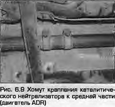
9. Remember the position of the clamp (the bolts should be to the left of the clamp, the lower ends of the bolts should be below the intermediate pipe), unscrew the clamp bolts and disconnect the catalytic converter from the middle part (Fig. 6.9).
Catalytic converter (aEB, AJL engines)
10. Remove the oxygen sensor. As noted in paragraph 4 of chapter 4A.
11. Unscrew the bolts securing the neutralizer to the inlet pipe and remove the gasket.
12. Remove the exhaust system bracket from the gearbox and lower the intake pipe.
13. Unscrew the flange nuts and remove the neutralizer from the turbine. Remove the gasket. Remove the neutralizer from under the car.
Short pipe (engines 1Z, AHU, ANN, AFN, AFF)
14. Loosen the flange mounting bolts and separate the exhaust pipe from the catalytic converter.
15. Loosen the clamp bolts and separate the short pipe from the middle section. Remove the short pipe from under the vehicle.
Middle part and muffler
16. Working under the vehicle, support the exhaust pipe with a jack or stand.
17. If the original pipe is installed, you will need to cut the middle section to separate it from the rear section with the muffler. The pipe has cut marks. Cut the pipe with a hacksaw or a cutting wheel at a right angle.
18. If the pipe has already been replaced, unscrew the clamp bolts and separate the middle pipe from the rear part.
19. Remember the position of the clamp that secures the middle part to the neutralizer (the bolts should be to the left of the clamp, the lower ends of the bolts should be below the pipe). Loosen the clamp bolts and separate the neutralizer.
20. Disconnect the rubber suspensions and remove the middle section with the muffler from under the car.
Rear part with muffler
21. If the original pipe is installed, you need to cut off the middle part to separate it from the rear part with the muffler. The pipe has marks of the cutting place. Cut the pipe with a hacksaw at a right angle.
22. If the pipe has already been replaced, unscrew the clamp bolts and separate the middle pipe from the rear part. Remember the position of the clamp: the bolts should be facing the rear of the car and the ends of the bolts should not protrude beyond the pipe.
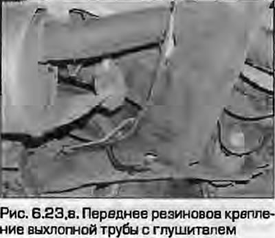
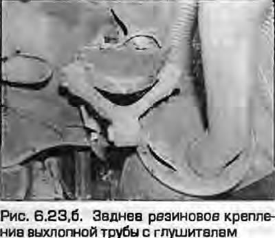
23. Disconnect the rubber pipe mounts and remove it from under the car (fig. 6.23, a, b).
 |
 |
Installation
24. Installation - reverse procedure. Please note the following.
- a) Remove all traces of corrosion from the flange connections and install new gaskets.
- b) Damaged rubber mounts must be replaced.
- c) Before tightening the mounting clamps, make sure that the rubber mounts are installed correctly and that there is sufficient clearance between the exhaust system and the body.
This article was copied from an online resource: Audimanual.ru