
Table of contents: Information ↓ Replacement of components ↓
Application: The system is installed on diesel engines only.
Information
1. The system consists of an EGR valve, a control valve and a set of various connecting vacuum hoses.
2. The EGR valve is installed on the intake manifold flange and is connected by another flange connection to the exhaust manifold using a semi-flexible tube.
Replacement of components
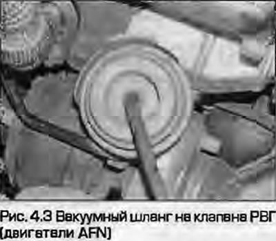
3. Disconnect the vacuum hose from the fitting on the EGR valve (Fig. 4.3).
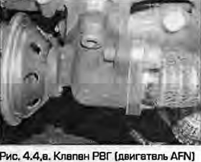
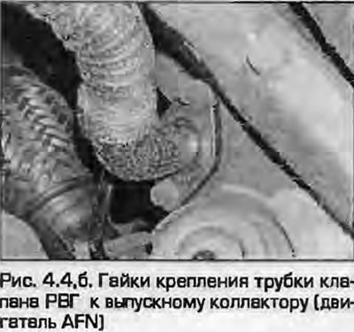
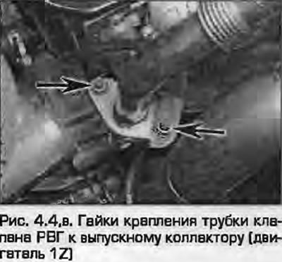
4. Unscrew the nuts and bolts and disconnect the semi-flexible connecting tube from the valve flange on the exhaust manifold side. The tube is connected to the intake manifold with two nuts, and to the EGR valve with two bolts (fig. 4.4, a-c). Remove the gaskets.
 |
 |
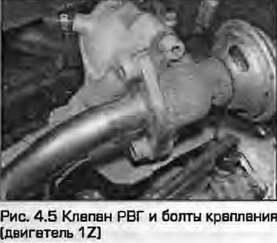
5. Unscrew the bolts securing the valve to the intake manifold flange and remove the valve (Fig. 4.5). Remove the gasket.
6. Installation - reverse procedure. Install new gaskets and new self-locking nuts.