
Table of contents: TD Diesel Engine ↓ EGR Solenoid Valve - Check ↓ Coolant Temperature Sensor - Check ↓ Partial Load Switch - Test ↓
A defect in the EGR system has virtually no effect on the operation of the power plant. For this reason, preventive checks of the EGR system are entirely appropriate.
TD Diesel Engine
1. Warm up the engine and let it idle.
The operation of the EGR system can be identified by the position of the mechanical EGR valve through the slot-shaped openings on the back of the valve diaphragm housing. If necessary, a flashlight can be shined into these openings (see illustration).
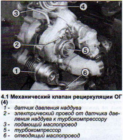
The piston of the mechanical valve should move towards the vacuum pump hose connection when the engine is idling. In this case, the exhaust gases are removed.
2. Have an assistant gradually increase the engine speed. As soon as the engine speed exceeds 1200 rpm, the piston of the mechanical valve should begin to move in the opposite direction from the vacuum pump hose connection, blocking the exhaust gas outlet for two seconds. After two seconds, the piston should move again to allow EGR.
3. Increase engine speed. At engine speeds above 3200 rpm, the partial load switch located on the high-pressure fuel pump is triggered. The piston of the mechanical EGR valve again moves in the opposite direction from the vacuum pump hose connection towards the intake manifold and remains in this position. No exhaust gas is removed. If the EGR does not function as described above, the power supply to the electromagnetic EGR valve should be checked.
4. Warm up the engine.
5. Disconnect the EGR solenoid valve power supply plug.
6. Connect the tester with LED light to the plug contacts.
7. Have an assistant start the engine. When the engine is idling, there should be power at the plug and the LED light should be on.
8. Ask an assistant to increase the engine speed. The control instrument LED should go out for two seconds. When the engine speed is increased again, the LED should not light.
If the LED tester lamp reacts differently to the voltage supplied to the plug, this may be caused by a defective coolant temperature sensor or partial load switch. This may also be caused by a defective electrical wiring of the specified components.
To check the condition of the mechanical EGR valve, a vacuum pump is required. The reduced pressure can be created by mouth, but this will require some effort.
9. Disconnect the vacuum supply hose from the vacuum pump from the valve.
10. Connect the vacuum pump and apply vacuum to the mechanical valve. The piston of the mechanical pump should begin to move towards the vacuum pump hose connection.
11. Apply air to the vacuum pump. The mechanical valve should close and be audible. If the characteristic noise of the valve closing is not audible, the valve is faulty and must be replaced.
EGR Solenoid Valve - Check
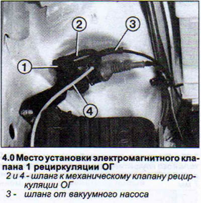
The EGR solenoid valve is located behind the air filter in the rear right side of the engine compartment (see illustration 4.0)
12. Warm up the engine and turn it off.
13. Set the ignition key to the "Warm Up" position. In this position of the ignition key, power is supplied to the vacuum pump - mechanical EGR valve circuit.
14. Disconnect the power plug of the electromagnetic EGR valve. In this case, the power supply to the vacuum pump - mechanical EGR valve circuit is interrupted and the voltage flows in a free direction.
Coolant Temperature Sensor - Check
The resistance of the sensor is measured, and for this you need an ohmmeter with a measurement range of 0-2000 Sigma.
15. Disconnect the sensor plug.
16. Measure the resistance between terminals A and C with an ohmmeter (see illustration and drawing).
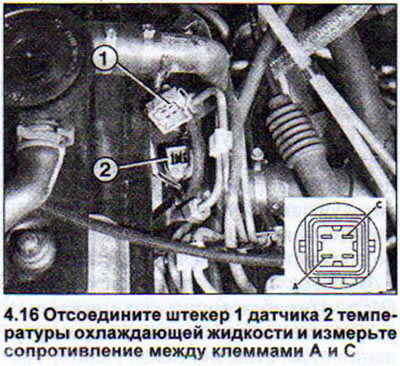
The resistance value depends on the coolant temperature. At a coolant temperature of 20°C it is 1000 - 1200 Sigma, and at 80°C it is 125 - 150 Sigma.
Partial Load Switch - Test
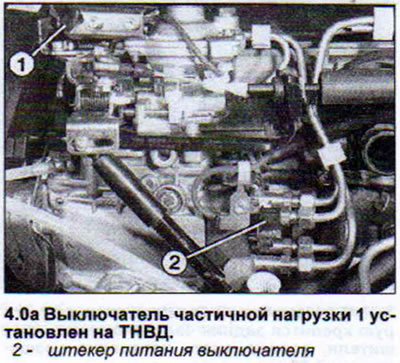
The partial load switch is installed on the injection pump above the pump control lever. The switch power plug is located at the bottom of the injection pump (see illustration 4.0a).
The resistance measurement of this switch is checked in the "Idle" and "Full Load" positions.
17. Disconnect the switch power plug.
18. Connect an ohmmeter to the switch contacts. The resistance on the contacts when the switch is in the "Idle" position is 0, and at full load the ohmmeter should show infinite resistance).
The switch is adjusted on the bench and its settings are not subject to adjustment. Adjustment of the new switch should be entrusted to the workshop.
(The original source of the article can be found on the website «AUDImanual»)