



1. Check the condition of the rubber cushions of the exhaust system suspension. Make sure that they do not have breaks, cracks or other damage. Replace the cushions if necessary.
2. Check the tightening of the bolts securing the exhaust pipe to the exhaust manifold (35 Nm), as well as the tightening of the bolts securing the exhaust pipe suspension bracket to the gearbox (25 Nm).
3. Plug the exhaust pipe opening with the engine running. The engine should stall after a short period of time. If the engine does not stall and hissing is heard, the exhaust system is not tight.
If the operation of the exhaust system is accompanied by more muffled sounds than usual, or if the system "shoots" when coasting, this indicates that the exhaust pipes are rusty.
Workshops usually prefer to replace the entire exhaust system as a set. We do not recommend doing this, because all the parts of the exhaust system can be purchased separately and replaced if they fail, provided that the entire system does not require replacement. Therefore, before changing the exhaust system, inspect it to make the right decision.
Welded seams of mufflers are most susceptible to corrosion.
4. Tap the mufflers on all sides with a hammer, and then, pressing with a screwdriver, make sure that the metal is not rusted and the muffler can still be used. If the metal of the muffler produces a clear sound when struck, then the part is normal. Dull sounds indicate that the upper metal shell of the muffler is quite corroded and it is possible that after some time it will "crumble", especially in winter, when the road surface is covered with a salt-containing mixture.
When replacing the exhaust system, the corresponding gaskets and self-locking nuts must be replaced with new ones.
Attention! In order to be able to unscrew the nuts and bolts without any problems the next time the exhaust system is dismantled, it is recommended to lubricate their threads with copper powder grease. The same applies to the mating sleeves, the inner surfaces of which are also recommended to be lubricated with the specified product.
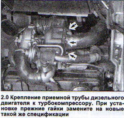
To avoid breaking the pins that hold the exhaust pipe when unscrewing tightly seated rusted nuts, it is recommended to first apply a rust converter and let it work. It is even easier to break the nut with a chisel. Nuts are usually made of soft metal (see arrows in illustration 2.0). When installing the exhaust pipe, replace the old nuts with new ones of the same specification. The tightening torque of the nuts on the exhaust pipe mounting pins is 35 Nm.
5. Remove the lambda probe. It must be removed when replacing the catalytic converter.
6. To do this, release the lambda probe power wire from the mount on the body and disconnect the plug.
7. Unscrew the lambda probe.
8. Lubricate the lambda probe before installing it in place with the G5 grease included in the repair kit. Do not allow the grease to get into the slot on the probe body. The tightening torque of the lambda probe is 50 Nm.
9. Unscrew the nuts securing the mating flange of the inlet pipe and the catalytic converter. This flange is usually shaped like a triangle (see illustrations 2.0a and 2.0b).
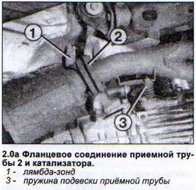
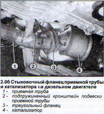
10. Unscrew the nuts securing the connecting flange. Be careful not to let the sealing ring fall out.
11. Observe the order of installation in the previous position of the springs and inserts on the exhaust system of six-cylinder engines.
12. Install the mating flange so that both halves are parallel to each other (see illustration 2.0v).
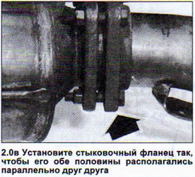
The tightening torque of the mating flange bolts is 25 Nm.
The clamp for fastening the joint of the inlet pipe and the main muffler is made in the form of a connecting sleeve, into which the pipes to be connected are inserted from both sides, with clamping clamps also at both ends. This type of pipe connection is quite easy and convenient to use.
Attention! The clamp securing the joint of the inlet pipe and the main muffler cannot be reinstalled. The clamp must be replaced even if the nut of only one clamp is unscrewed.
13. Remember the mounting position of the clamp before disconnecting it (see illustration).
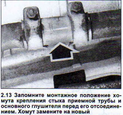
14. Unscrew the nuts of both clamps. If necessary, apply a rust converter. If necessary, the bolts can be cut or the nuts can be broken with a chisel. The tightening torque of the clamp nuts is 40 Nm.
15. Mark or remember the mounting position of the clamps before disconnecting and removing them (see illustrations 2.15 and 2.15a).
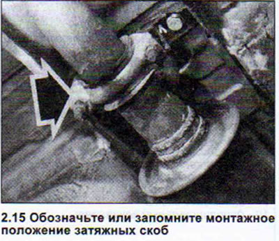
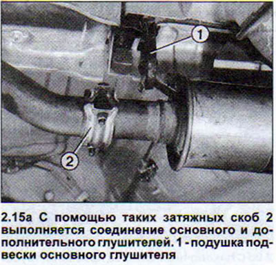
16. Loosen the clamp nuts. Be careful not to let the sealing ring fall out.
17. When installing the clamping brackets, make sure that their position corresponds to the one they were in before removal and that they are well "sat" on the fixed joint. The tightening torque of the clamp nuts is 25 Nm.
Exhaust system silencers for Quattro vehicles
The main and additional mufflers on Quattro vehicles are connected to each other by a solid pipe. The mufflers can be replaced separately. To do this, the connecting pipe must be cut. Illustration 2.0g shows the procedure for disconnecting the mufflers on Quattro vehicles.
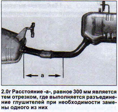
18. Cut the pipe, holding the saw at a right angle. It is almost impossible to cut the connecting pipe of the mufflers on Quattro cars without dismantling the mufflers due to difficult access.
19. Disconnect the main and additional mufflers.
20. Connect the pipes of the main and additional mufflers using the clamp that is used to connect the inlet pipe and the main muffler (see illustration 2.13). The tightening torque of the clamp bolts is 25 Nm.
Exhaust pipes and mufflers installed under stress may cause knocking noises while driving.
21. Place the pipes and mufflers on the retaining tabs and align them properly before tightening the mounting bolts.
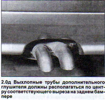
Attention! All parts of the exhaust system must be located at a sufficient distance from the bottom, providing access to the body. Exhaust pipe (exhaust pipes) the additional muffler must be equally spaced around the entire circumference from the edges of the corresponding cutout in the rear bumper (see illustration 2.0d).
22. Tighten the bolts securing the intake pipe bracket to the gearbox with a torque of 25 Nm, without allowing the bracket to become stressed
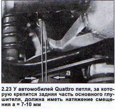
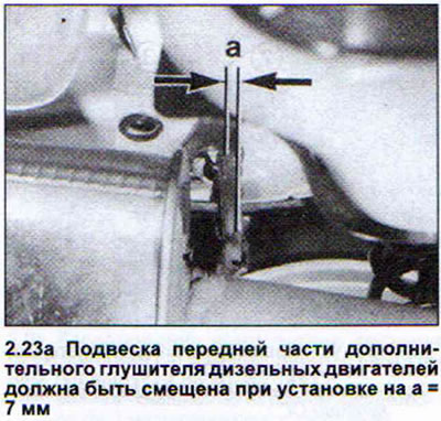
23. Observe the offset tension. On Quattro vehicles, the suspension loop of the rear part of the main silencer must have an offset tension of 710 mm. The suspension loop of the front part of the additional silencer on diesel engines must also have an offset of 7 mm. On front-wheel drive vehicles, the suspension bolt of the rear part of the exhaust system must protrude from the rubber cushion by approximately 10 mm. When the engine warms up to operating temperature, the suspension of the exhaust system expands and the system aligns itself, assuming a vertical position (see illustrations).
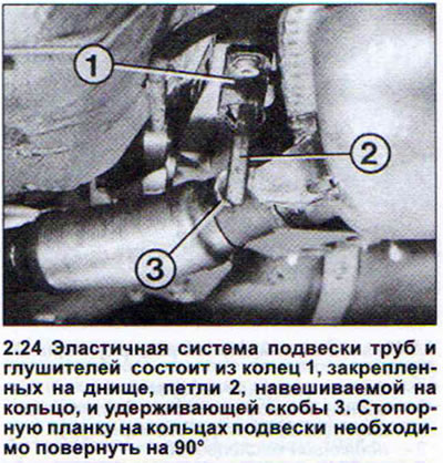
24. Rotate the locking bar on the rings on which the pipe and muffler suspension loops are hung by approximately 90°. Make sure that the ring is not jammed (see illustration).
25. Tighten all exhaust system mounting bolts, starting from the muffler inlet pipe, to the specified tightening torques.
(The original version is on the portal «AUDIMANUAL»)