



EP, YP, YZ, DT, DS, DZ car engines Audi 80 B2

Design and technical characteristics. General information
The four-stroke, four-cylinder, carburetor, in-line engine is installed inclined to the right along the longitudinal axis of the vehicle. The cooling system is...
The four-stroke, four-cylinder, carburetor, in-line engine is installed inclined to the right along the longitudinal axis of the vehicle. The cooling system is...

Cylinder head specifications
The cylinder head without combustion chambers is cast from aluminum alloy. When casting, the heads are marked with a part number. The valve seats and guide...
The cylinder head without combustion chambers is cast from aluminum alloy. When casting, the heads are marked with a part number. The valve seats and guide...

Technical characteristics of the cylinder block
The cylinder block is sleeveless and cast iron. The lower part of the cylinder block has five supports for the crankshaft main bearing shells. The main bearing...
The cylinder block is sleeveless and cast iron. The lower part of the cylinder block has five supports for the crankshaft main bearing shells. The main bearing...

Technical characteristics of the crank mechanism
Crankshaft The crankshaft is steel, forged. The shaft has five bearings. There are lubrication grooves in the upper liners of the main bearings. The axial...
Crankshaft The crankshaft is steel, forged. The shaft has five bearings. There are lubrication grooves in the upper liners of the main bearings. The axial...

Technical characteristics of the valve timing mechanism
The engine uses a valve timing mechanism with an overhead camshaft, the drive of which is carried out by a toothed belt from the crankshaft pulley. The belt...
The engine uses a valve timing mechanism with an overhead camshaft, the drive of which is carried out by a toothed belt from the crankshaft pulley. The belt...

Technical characteristics of the lubrication system
The engines have a pressure lubrication system. Under the action of vacuum, oil is sucked from the oil sump through a mesh filter: oil receiver by a gear oil...
The engines have a pressure lubrication system. Under the action of vacuum, oil is sucked from the oil sump through a mesh filter: oil receiver by a gear oil...
Technical characteristics of the cooling system
The engine uses a liquid cooling system with forced circulation. The cooling system includes an engine water jacket, a radiator, an expansion tank, a...
The engine uses a liquid cooling system with forced circulation. The cooling system includes an engine water jacket, a radiator, an expansion tank, a...
Technical characteristics of the power supply system
Fuel tank The fuel tank is stamped from sheet steel. Fuel tank capacity, l: 68.
Fuel tank The fuel tank is stamped from sheet steel. Fuel tank capacity, l: 68.
Technical characteristics of carburetor engines
Fuel pump The mechanical diaphragm type fuel pump is driven by an eccentric on the intermediate shaft. Brand: Pierburg. Fuel supply pressure at crankshaft...
Fuel pump The mechanical diaphragm type fuel pump is driven by an eccentric on the intermediate shaft. Brand: Pierburg. Fuel supply pressure at crankshaft...

Technical characteristics of the Zenith 2B2 carburetor
Up to the 1980 model year, the engine was equipped with a Zenith 2B2 carburetor. The carburetor is an emulsion type, two-chamber, with sequential opening of...
Up to the 1980 model year, the engine was equipped with a Zenith 2B2 carburetor. The carburetor is an emulsion type, two-chamber, with sequential opening of...

Technical characteristics of the Zenith 2B5 carburetor
Since the 1980 model year, the YP engine was equipped with a Pierburg 2B5 emulsion-type carburetor, two-chamber, with sequential opening of the throttle...
Since the 1980 model year, the YP engine was equipped with a Pierburg 2B5 emulsion-type carburetor, two-chamber, with sequential opening of the throttle...

Technical characteristics of the Keihin 26-30 DC carburetor
The EP engine was equipped with a Keihin 26-30 DC emulsion-type carburetor, two-chamber, with sequential opening of the throttle valves. The carburetor has two...
The EP engine was equipped with a Keihin 26-30 DC emulsion-type carburetor, two-chamber, with sequential opening of the throttle valves. The carburetor has two...

Technical characteristics of the Pierburg 2E2 carburetor
The DT and DS engines were equipped with a Pierburg 2E2 emulsion-type carburetor, two-chamber, with sequential opening of the throttle valves. The carburetor...
The DT and DS engines were equipped with a Pierburg 2E2 emulsion-type carburetor, two-chamber, with sequential opening of the throttle valves. The carburetor...
Technical characteristics of engines with the K-Jetronic fuel injection system
The YZ and 0Z engines are equipped with the K-Jetronic mechanical continuous fuel injection system from Bosch. The principle of operation of the fuel injection...
The YZ and 0Z engines are equipped with the K-Jetronic mechanical continuous fuel injection system from Bosch. The principle of operation of the fuel injection...
Technical characteristics of the contact ignition system
Until the 1980 model year, the YP and YZ engines were equipped with a contact ignition system. The engine ignition system is battery-operated, contact, with a...
Until the 1980 model year, the YP and YZ engines were equipped with a contact ignition system. The engine ignition system is battery-operated, contact, with a...

Technical characteristics of the contactless ignition system
Since the 1980 model year, the YP, YZ engines, as well as the EP, DT, DS and DZ engines, were equipped with a contactless ignition system, including a...
Since the 1980 model year, the YP, YZ engines, as well as the EP, DT, DS and DZ engines, were equipped with a contactless ignition system, including a...
Tightening torques of main threaded connections, kgf.m
Cylinder head mounting bolts* (on a cold engine): 1st reception: 4.0; 2nd reception: 6.0; 3rd reception: 7.5; step 4: Turn 90° further. Crankshaft timing...
Cylinder head mounting bolts* (on a cold engine): 1st reception: 4.0; 2nd reception: 6.0; 3rd reception: 7.5; step 4: Turn 90° further. Crankshaft timing...

Checking and adjusting clearances in the valve drive mechanism
Engines YP, YZ, EP and OT, DS, DZ before July 1985. Warm up the engine (coolant temperature 35°C, cylinder head warm). Remove the cylinder head cover. Turn the...
Engines YP, YZ, EP and OT, DS, DZ before July 1985. Warm up the engine (coolant temperature 35°C, cylinder head warm). Remove the cylinder head cover. Turn the...

Construction of hydraulic tappets
The hydraulic pusher consists of two main moving parts: the pusher itself 2 (see picture), serving simultaneously in the process of work of the plunger, and...
The hydraulic pusher consists of two main moving parts: the pusher itself 2 (see picture), serving simultaneously in the process of work of the plunger, and...

Operating principle of hydraulic tappets
Valve lift start moment At the moment the camshaft cam hits the valve stem, the check valve closes the chamber and the pressure in it increases. The increase...
Valve lift start moment At the moment the camshaft cam hits the valve stem, the check valve closes the chamber and the pressure in it increases. The increase...

Checking the technical condition of hydraulic tappets
The hydraulic tappet design is non-disassemblable and cannot be repaired. Start the engine and leave it running until the electric cooling fan turns on for the...
The hydraulic tappet design is non-disassemblable and cannot be repaired. Start the engine and leave it running until the electric cooling fan turns on for the...
Carburetor engines
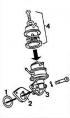
Fuel pump The fuel pump is secured with two nuts through a heat-insulating gasket and a sealing ring. The pump body and cover are non-separable, i.e. the pump...
Fuel pump The fuel pump is secured with two nuts through a heat-insulating gasket and a sealing ring. The pump body and cover are non-separable, i.e. the pump...
Carburetor Zenith 2B2
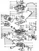
The design features and calibration data of carburetors are given in the subsection " Design and technical characteristics ". Operating principle of the...
The design features and calibration data of carburetors are given in the subsection " Design and technical characteristics ". Operating principle of the...

Checking and adjusting the Zenith 2B2 carburetor
Checking the fuel level in the float chambers Remove the carburetor cover and turn it over. Measure the distance between the plane of the carburetor cover and...
Checking the fuel level in the float chambers Remove the carburetor cover and turn it over. Measure the distance between the plane of the carburetor cover and...

Operating principle of the Pierburg 2B5 carburetor
Starting device When starting a cold engine, under the influence of the thermostatic bimetallic spring of the automatic starting device, the air damper 1 (see...
Starting device When starting a cold engine, under the influence of the thermostatic bimetallic spring of the automatic starting device, the air damper 1 (see...

Checking and adjusting the Pierburg 2B5 carburetor
Adjusting the fuel level in the float chambers Remove the carburetor cover and turn it over. Measure the distance between the plane of the carburetor cover and...
Adjusting the fuel level in the float chambers Remove the carburetor cover and turn it over. Measure the distance between the plane of the carburetor cover and...

Adjusting the idle speed of a warm engine
Adjusting engine idle speed Adjustment of the engine idle speed is performed on a warmed-up engine (oil temperature not less than 60°C), with the air damper...
Adjusting engine idle speed Adjustment of the engine idle speed is performed on a warmed-up engine (oil temperature not less than 60°C), with the air damper...

Operating principle of the Keihin 26-30 DC carburetor
Starting device Enrichment of the combustible mixture when starting a cold engine is ensured by closing the air damper 1 (see diagram) with an offset axis. The...
Starting device Enrichment of the combustible mixture when starting a cold engine is ensured by closing the air damper 1 (see diagram) with an offset axis. The...

Checking and adjusting the Keihin 26-30 DC carburetor
Adjusting the starting clearance of the air damper Pull the choke control handle out fully; in this case, the air damper control lever should be at the stop....
Adjusting the starting clearance of the air damper Pull the choke control handle out fully; in this case, the air damper control lever should be at the stop....

Operating principle of the Pierburg 2E2 carburetor
Starting device Under the action of the thermostatic bimetallic spring of the automatic starting device, the air damper 1 (see diagram) blocks the flow of air...
Starting device Under the action of the thermostatic bimetallic spring of the automatic starting device, the air damper 1 (see diagram) blocks the flow of air...

Checking and adjusting the Pierburg 2E2 carburetor
Checking the fuel level in the float chamber The position of the float in the float chamber is not adjustable. If a malfunction is detected, check the...
Checking the fuel level in the float chamber The position of the float in the float chamber is not adjustable. If a malfunction is detected, check the...

Engines with the K-Jetronic fuel injection system
Features of the device and the operating principle of the "K-Jetronic" system Components of the K-Jetronic fuel injection system: 1 - mixture regulator (a unit...
Features of the device and the operating principle of the "K-Jetronic" system Components of the K-Jetronic fuel injection system: 1 - mixture regulator (a unit...

Checking and adjusting the K-Jetronic system
Adjusting the throttle opening Note: The throttle opening is adjusted at the factory and cannot be changed during operation. However, if the stop screw is...
Adjusting the throttle opening Note: The throttle opening is adjusted at the factory and cannot be changed during operation. However, if the stop screw is...

YZ Engine Cars with Contact Ignition System
Engine crankshaft speed control at idle Connect the tachometer according to the operating instructions. Turn on the high beam headlights. Start the engine and...
Engine crankshaft speed control at idle Connect the tachometer according to the operating instructions. Turn on the high beam headlights. Start the engine and...

Vehicles with YZ engine with contactless ignition system and digital idle speed stabilizer
Connect the tachometer according to the operating instructions. Disconnect the wires from the digital idle speed control (DSC) located on the upper front panel...
Connect the tachometer according to the operating instructions. Disconnect the wires from the digital idle speed control (DSC) located on the upper front panel...

Cars with DZ engine
Connect the tachometer according to the operating instructions. Warm up the engine to operating temperature. Clamp the hose going to the idle speed control...
Connect the tachometer according to the operating instructions. Warm up the engine to operating temperature. Clamp the hose going to the idle speed control...
Checking the performance of the fuel pump
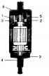
Disconnect the drain hose from the supply pressure regulator on the fuel dispenser and lower its end and the measuring cup. Disconnect the high tension wire...
Disconnect the drain hose from the supply pressure regulator on the fuel dispenser and lower its end and the measuring cup. Disconnect the high tension wire...

Adjusting the position of the air flow meter pressure disc
Make sure that when the engine is not running, the pressure disk is level or no more than 0.5 mm below the beginning of the expanding cone of the air flow...
Make sure that when the engine is not running, the pressure disk is level or no more than 0.5 mm below the beginning of the expanding cone of the air flow...

Pressure check
To check the pressure, use a VW 1318 pressure gauge with a fitting and a tap that measures both the flow pressure and the inlet pressure. Connect the pressure...
To check the pressure, use a VW 1318 pressure gauge with a fitting and a tap that measures both the flow pressure and the inlet pressure. Connect the pressure...

Checking injection nozzles
Unscrew the nozzle from the socket and screw in a spare nozzle in its place. Lower the nozzle into the measuring cup. Start the engine, let it run at a...
Unscrew the nozzle from the socket and screw in a spare nozzle in its place. Lower the nozzle into the measuring cup. Start the engine, let it run at a...

Checking the starting injector and thermal time relay
Disconnect the connector from the starting injector and connect a test lamp to it. Disconnect the high voltage wire from the ignition coil. Turn on the...
Disconnect the connector from the starting injector and connect a test lamp to it. Disconnect the high voltage wire from the ignition coil. Turn on the...
Checking the control pressure regulator
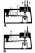
Warm up the engine (oil temperature 50-70°C). Disconnect the connector from the control pressure regulator and connect a voltmeter to the connector. Turn on...
Warm up the engine (oil temperature 50-70°C). Disconnect the connector from the control pressure regulator and connect a voltmeter to the connector. Turn on...

Checking the idle speed control valve
Note: The test is performed on a warm engine. Disconnect the idle speed control valve connector and connect a voltmeter to the connector terminals (see fig.)....
Note: The test is performed on a warm engine. Disconnect the idle speed control valve connector and connect a voltmeter to the connector terminals (see fig.)....

Checking the additional air supply valve
On a cold engine (at a coolant temperature below 30°C), disconnect the block from the additional air supply valve. Disconnect the hose from the intake manifold...
On a cold engine (at a coolant temperature below 30°C), disconnect the block from the additional air supply valve. Disconnect the hose from the intake manifold...

Electrical circuit of the fuel injection system «K-Jetronic»
The circuit is open: 1 - ignition switch; 2 - electromagnetic starting nozzle; 3 - thermal time relay; 4 - fuel pump relay; 5 - fuel electric pump; 6 - control...
The circuit is open: 1 - ignition switch; 2 - electromagnetic starting nozzle; 3 - thermal time relay; 4 - fuel pump relay; 5 - fuel electric pump; 6 - control...

Adjusting the gaps between the breaker contacts
Remove the distributor cap and rotor. Make sure that the contact surfaces are smooth, strictly parallel and fit together over the entire surface. Replace...
Remove the distributor cap and rotor. Make sure that the contact surfaces are smooth, strictly parallel and fit together over the entire surface. Replace...
Checking the contactless ignition system switch
Disconnect the wires from the digital idle stabilizer move (if it is installed) and connect them together. Disconnect the central high-voltage wire from the...
Disconnect the wires from the digital idle stabilizer move (if it is installed) and connect them together. Disconnect the central high-voltage wire from the...
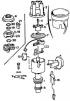
Checking the distributor sensor of the contactless ignition system
First check the serviceability of the switch. Disconnect the wires from the digital idle speed controller (if it is installed) and connect them together....
First check the serviceability of the switch. Disconnect the wires from the digital idle speed controller (if it is installed) and connect them together....

Timing mechanism: removing and installing the camshaft drive belt
Removal Loosen the generator mounting bolts, loosen and remove the generator drive belt. Remove the crankshaft pulley. Depending on the engine model, remove...
Removal Loosen the generator mounting bolts, loosen and remove the generator drive belt. Remove the crankshaft pulley. Depending on the engine model, remove...

Removal the cylinder head
Disconnect the wire from the negative terminal of the battery. Place a container under the engine to collect the coolant and drain the coolant from the cooling...
Disconnect the wire from the negative terminal of the battery. Place a container under the engine to collect the coolant and drain the coolant from the cooling...

Installing the cylinder head
Note: Replace the sealing gaskets each time the cylinder head is removed. Install a new cylinder head gasket with the "oben" ("top") mark facing the plane of...
Note: Replace the sealing gaskets each time the cylinder head is removed. Install a new cylinder head gasket with the "oben" ("top") mark facing the plane of...

Disassembly and repair of the cylinder head
When disassembling the cylinder head, mark the parts to be removed so that they can be put back in their original places when reassembling. Remove bearing caps...
When disassembling the cylinder head, mark the parts to be removed so that they can be put back in their original places when reassembling. Remove bearing caps...

Cylinder head assembly
Install the valve spring support washers in place using 10-218 pliers and insert the valves into the guide bushings, having first lightly lubricated the valve...
Install the valve spring support washers in place using 10-218 pliers and insert the valves into the guide bushings, having first lightly lubricated the valve...

Removal and installation of carburetor engines
Removal Place the engine on a lift and remove the hood. Disconnect the wire from the negative terminal of the battery. Set the heater control handle to the...
Removal Place the engine on a lift and remove the hood. Disconnect the wire from the negative terminal of the battery. Set the heater control handle to the...

Disassembling the engine
Note: When disassembling, apply marks to the removed parts that are suitable for further use, so that when reassembling, they can be installed in their...
Note: When disassembling, apply marks to the removed parts that are suitable for further use, so that when reassembling, they can be installed in their...

Engine assembly
Checking cylinder diameters Accurately measure the cylinder diameters. Measurements are taken with a bore gauge in three zones both in the transverse direction...
Checking cylinder diameters Accurately measure the cylinder diameters. Measurements are taken with a bore gauge in three zones both in the transverse direction...

Checking the clearances between the bearings and the crankshaft journals
Inspect the crankshaft. Cracks, scratches, nicks and marks on the crankshaft are not allowed. Thoroughly clean the working surfaces of the bearings and the...
Inspect the crankshaft. Cracks, scratches, nicks and marks on the crankshaft are not allowed. Thoroughly clean the working surfaces of the bearings and the...

Engine assembly
Place the liners with a groove on the inner surface into the main bearing seats (see photo). Lubricate the main journals of the crankshaft with engine oil and...
Place the liners with a groove on the inner surface into the main bearing seats (see photo). Lubricate the main journals of the crankshaft with engine oil and...
Replacing the oil filter
Loosen the threads on the oil filter housing using a device with a band or clamp clamp. Remove the device and unscrew the filter. Lubricate the filter gasket...
Loosen the threads on the oil filter housing using a device with a band or clamp clamp. Remove the device and unscrew the filter. Lubricate the filter gasket...

Removal and installation the oil pump
Removal the oil pump The oil pump can be removed directly from the vehicle. Drain the oil from the engine crankcase. Remove the oil pan. Loosen the bolts...
Removal the oil pump The oil pump can be removed directly from the vehicle. Drain the oil from the engine crankcase. Remove the oil pan. Loosen the bolts...

Disassembly, inspection of technical condition and assembly of the oil pump
Unscrew the two bolts securing the oil pump cover to the housing. Separate the cover from the body. Remove the drive shaft and the drive gear of the oil pump....
Unscrew the two bolts securing the oil pump cover to the housing. Separate the cover from the body. Remove the drive shaft and the drive gear of the oil pump....
Checking the oil pressure in the lubrication system
Disconnect the wires from the oil pressure sensor, remove the sensor and screw in the fitting of the control pressure gauge hose in its place. Start the engine...
Disconnect the wires from the oil pressure sensor, remove the sensor and screw in the fitting of the control pressure gauge hose in its place. Start the engine...

Replacing the coolant
Place a container under the engine to collect the coolant. Set the heater control handle to the extreme right position. Remove the plug from the radiator 1 or...
Place a container under the engine to collect the coolant. Set the heater control handle to the extreme right position. Remove the plug from the radiator 1 or...

Removal and installation the water pump
Drain the fluid from the cooling system. Disconnect the wire from the negative terminal of the battery. Remove the generator. Disconnect the hoses from the...
Drain the fluid from the cooling system. Disconnect the wire from the negative terminal of the battery. Remove the generator. Disconnect the hoses from the...

Disassembly and assembly of the water pump
Remove the pump drive pulley. Loosen the bolts securing the pump cover and remove it together with the bushing, shaft and impeller, detach the cover from the...
Remove the pump drive pulley. Loosen the bolts securing the pump cover and remove it together with the bushing, shaft and impeller, detach the cover from the...
Adjusting the alternator drive belt tension
Loosen the bolts securing the generator bracket and tension bar. Move the generator away from the cylinder block and tighten the generator mounting bolt to the...
Loosen the bolts securing the generator bracket and tension bar. Move the generator away from the cylinder block and tighten the generator mounting bolt to the...
This section is available on russian, bulgarian, belarusian, ukrainian, serbian, croatian, romanian, polish, slovak, hungarian
Similar sections of other Audi car models:
Power unit: Engine in a car Audi 100 C3 (1982-1990, diesel)
Power unit: Engine repair Audi A3 Type 8L (1996-2003)
Power unit: Engine repair Audi A4 B6 (2000-2006, petrol)
Gasoline engines: 6 cylinder engines Audi A6 C4 (1994-1997)
Engine 1.4 l (diesel): Engine repair Audi A2 (1999-2005)
Power unit: Engine in a car Audi 100 C3 (1982-1990, diesel)
Power unit: Engine repair Audi A3 Type 8L (1996-2003)
Power unit: Engine repair Audi A4 B6 (2000-2006, petrol)
Gasoline engines: 6 cylinder engines Audi A6 C4 (1994-1997)
Engine 1.4 l (diesel): Engine repair Audi A2 (1999-2005)
Share information:
- General information
- User manual
- Maintenance
- Troubleshooting
- Power unit
- Engine
- Cooling system
- Heating and ventilation
- Petrol injection
- Diesel fuel system
- Fuel system
- Exhaust systems
- Ignition system
- Transmission
- Clutch
- Car gearbox
- Chassis
- Brake system
- Suspension and steering wheel
- Body
- Body and trim
- Electrical equipment
- Electrical system
- Electrical circuits
- General information
- Repair characteristics
- Maintenance
- Power unit
- Gasoline engine
- Diesel engine
- Engine lubrication system
- Fuel system (gasoline)
- Injection system (gasoline)
- Fuel system (diesel)
- Ignition system
- Cooling system
- Heater
- Exhaust system
- Transmission
- Clutch and gearbox
- Chassis
- Steering
- Brake system
- Car suspension
- Body
- Body elements
- Electrical equipment
- Power devices
- Lighting and appliances
- Electrical circuits
- General information
- User manual
- Maintenance
- Power unit
- Engine 4-cylinder
- Engine 5-cylinder
- Cooling system
- Fuel and exhaust systems
- Ignition system
- Transmission
- Clutch
- Mechanical transmission
- Automatic transmission
- Drive shafts
- Chassis
- Brake system
- Suspension
- Steering
- Body
- Exterior
- Interior
- Electrical equipment
- Equipment and devices
- Electrical circuits