



Table of contents: Operating principle of the starting… ↓ Cold engine start ↓ Warming up the engine ↓ Idling a warm engine ↓
The design features and calibration data of carburetors are given in the subsection "Design and technical characteristics".
Operating principle of the starting device
The automatic starting device reduces the amount of harmful emissions in the exhaust gases, improves the operation of a cold engine at idle. The air and throttle valves do not have a rigid connection.
Cold engine start
When the air damper is closed, the throttle control lever rests against the shaped sector. The throttle valve is open, an enriched fuel-air mixture enters the engine, providing a fast idle mode.
Warming up the engine
The air damper is fully open, the idle air-fuel mixture is leaning. The throttle control lever still rests against the shaped sector. The throttle valve is slightly open and the engine operates in fast idle mode.
Idling a warm engine
The throttle control lever has left the shaped sector. The throttle valve is closed and the engine operates in normal idle mode.
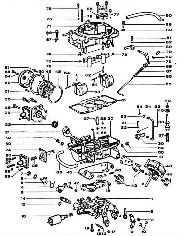
Main parts of the Zenith 2B2 carburetor: 1 — throttle body; 2 — 1st chamber throttle valve opening control lever; 3 — adjusting screw of the starting gap of the throttle valve of the 1st chamber; 9 — 2nd chamber throttle control lever; 11 — roller; 12 — adjusting screw for idle mixture quality (composition); 13, 15 — sealing rings; 14 — idle mixture quantity adjusting screw; 16 - electromagnetic shut-off valve; 18 - insulating gasket; 20 — carburetor body; 23 — pneumatic drive of the air damper; 24 — valve diaphragm; 26 — pneumatic drive cover; 27 — valve adjusting screw; 30 — air damper control lever; 33 — air damper connection; 36 — vacuum supply hose; 38 — accelerator pump piston; 43 — pneumatic drive of the throttle valve of the 1st chamber; 46 — throttle valve opening limit screw; 48 - Automatic starting device gasket; 49 — automatic starting device housing; 50 — mounting flange; 52 — Automatic starting device cover; 55 — valve ball; 57 - accelerator pump nozzle; 58 - sealing gasket; 59 - threaded plug; 61 - Carburetor cover gasket; 62 - needle valve; 63 - float; 64 — float axis; 65 — accelerator pump control rod; 67 — accelerator pump thrust spring; 68 - guide bushing; 70 - adjusting nut; 71 — carburetor cover; 72 - small diffuser; 73 - small diffuser spring latch; 74 - main fuel jets; 75 - main air jet; 76 - idle air jet; 77, 78 — idle fuel jets; 79 — accelerator pump control lever; 80 — accelerator pump lever pusher; 85 - atmospheric hole cover.
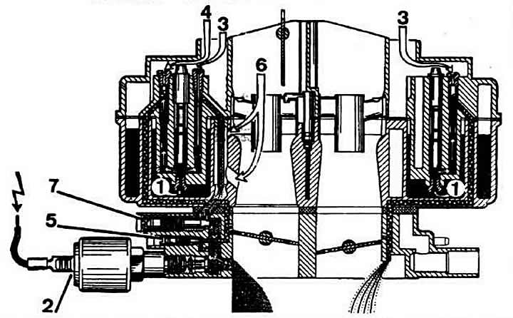
Diagram of the idle system of the Zenith 2B2 carburetor: 1 - main fuel jets; 2 - electromagnetic shut-off valve; 3 — idling system air supply; 4 - additional air intake; 5 - adjusting the quality (composition) of the mixture; 6 — idle system air intake; 7 — mixture quantity adjustment screw.
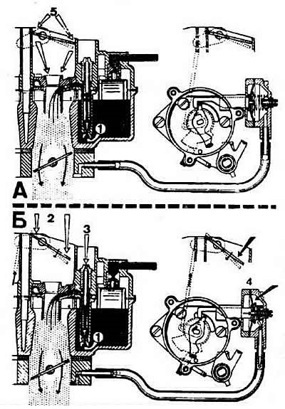
Operating diagram of the Zenith 2B2 carburetor starting device: A - when starting a cold engine; B - when warming up the engine. 1 - main fuel jet; 2.5 - main air supply; 3 - emulsion air supply; 4 - both long valve.
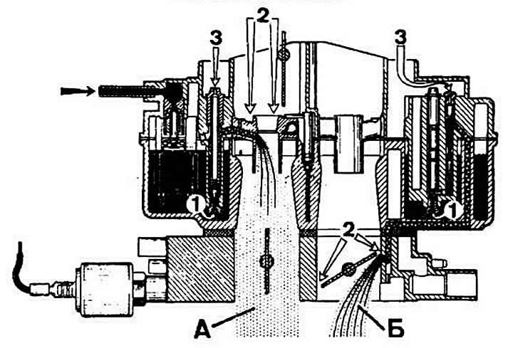
The operation diagram of the Zenith 2B2 carburetor at the moment of switching on the main dosing system of the 2nd chamber: A - 1st chamber; B - 2nd chamber; 1 - main fuel jets; 2 - main air supply; 3 - supply of emulsion air.
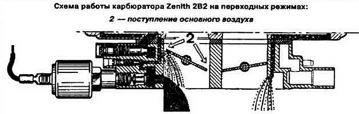
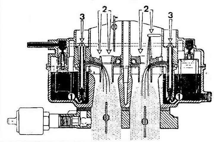
Diagram of the main metering systems of the Zenith 2B2 carburetor: 1 - main fuel jets; 2 - main air supply; 3 - supply of emulsion air.
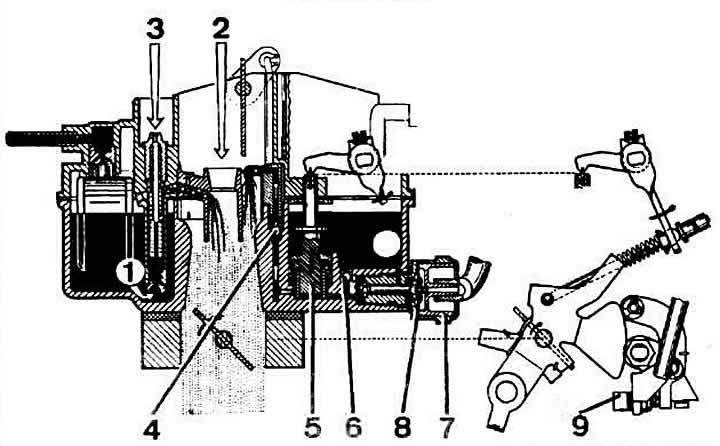
Schematic diagram of the accelerator pump and dual feed valve of the Zenith 2B2 carburetor: 1 - main fuel jet; 2 - main air supply; 3 - emulsion air supply; 4 - discharge valve; 5 — accelerator pump piston; 6 - suction valve; 7 - dual supply valve; 8 - diaphragm; 9 — adjusting screw.
(The text is based on materials from the website AUDIMANUAL.ru)