Table of contents: Adjusting the fuel level in the… ↓ Adjusting the idle speed of a cold… ↓ Adjusting the starting clearances of… ↓ Adjusting the opening of the… ↓ Adjusting the opening of the… ↓ Adjusting the accelerator pump ↓ Adjusting the throttle control lever… ↓
Adjusting the fuel level in the float chambers
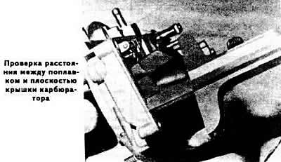
Remove the carburetor cover and turn it over.
Measure the distance between the plane of the carburetor cover and the lower point of the floats, which for the 1st chamber should be within 28±1 mm, for the 2nd chamber - 30±1 mm. If it does not correspond to this, set the required size by bending the tongues of the float levers.
Adjusting the idle speed of a cold engine
Warm up the engine to operating temperature.
Connect the tachometer.
Stop the engine.
Remove the air filter.
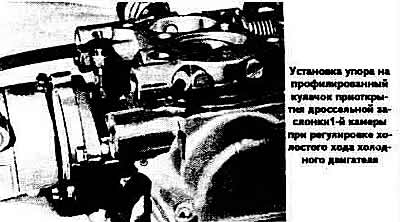
Open the throttle valve of the 1st chamber and close the air damper by pressing the throttle valve opening cam (see photo).
Release the throttle valve of the 1st chamber.
Start the engine without pressing the accelerator pedal.
Measure the crankshaft speed, which should be within 3350-3450 rpm.
If necessary, adjust the starting clearance of the throttle valve of the 1st chamber using the limiting screw resting on the profiled cam for opening the throttle valve.
The starting gap should be within 0.65±0.052 mm.
Adjusting the starting clearances of the air damper
Remove the starter cover.
Open the throttle valve completely, placing the cam slightly open on the corresponding profile and the throttle valve.
Connect a vacuum gauge and a vacuum pump to the air damper pneumatic drive and create a vacuum of 100 mbar in the pneumatic drive.
If the air damper pneumatic drive is hermetically sealed, the vacuum should not decrease by more than 5 mbar per minute and should decrease below 40 mbar.
Bring the vacuum in the air damper pneumatic drive to 200-300 mbar.
Using a set of feeler gauges, measure the starting gap of the first stage of the air damper, which should be within 1.8±0.15 mm.
If necessary, set the required clearance using the pneumatic drive diaphragm stroke adjustment screw located on its cover.
Close the atmospheric hole of the air damper pneumatic drive with a plug, create a vacuum of 200 mbar in the pneumatic drive, which, if the pneumatic drive is sealed, should remain unchanged for at least 1 min.
Measure the starting gap of the second stage of the air damper using a set of feeler gauges; it should be within 3.9±0.15 mm.
If there is a deviation from the norm, set the proper clearance using the pneumatic drive diaphragm stroke adjustment screw located on the end of the air damper pneumatic drive rod.
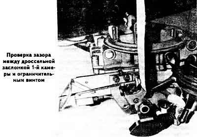
Adjusting the opening of the throttle valve of the 1st chamber
The position of the throttle valve of the 1st chamber is adjusted at the factory, but if the adjustment is violated, it can be restored as follows:
- remove the throttle valve limit screw plug;
- move the throttle control lever stop away from the profiled choke control lever, fully opening the choke;
- turn the limit screw so that it does not touch the throttle control lever;
- open the throttle;
- screw the limit screw until it touches the throttle control lever, then screw it in another ¼ turn. If the throttle opening is adjusted correctly, the gap between the limit screw and the throttle control lever should be 0.05 mm;
- install a new plug on the throttle stop screw.
Adjusting the opening of the throttle valve of the 2nd chamber
The position of the throttle valve of the 2nd chamber is adjusted at the factory, but if the adjustment is disturbed, it can be restored as follows:
- unscrew the limit screw of the 2nd chamber throttle valve so that it moves away from the stop, then screw in the limit screw so that it barely touches the stop;
- disconnect the rod from the pneumatic drive of the throttle valve of the 2nd chamber;
- turn the limit screw ¼ turn;
- lock the limit screw with special glue or paint.
Adjusting the accelerator pump
Remove the carburetor.
Fully push in the movable rod of the pneumatic drive of the DRBS-Selion valve of the 1st chamber and turn the cam for opening the throttle valve of the 1st chamber so as to release the throttle valve and open it fully.
Place a measuring cup under the carburetor.
Smoothly open and close the throttle valve of the first chamber ten times, thereby activating the accelerator pump.
Measure the amount of fuel in the measuring cup, which should be 10±1.5 cm³, i.e. 1.0±0.15 cm³ per cycle.
If necessary, adjust the required performance of the accelerator pump by moving the pump drive cam on the 1st chamber throttle control lever.
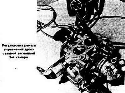
Adjusting the throttle control lever of the 2nd chamber
Remove the carburetor.
Set the throttle valves of both chambers to the idle position of a warm engine: the air damper should be open and the throttle valves closed.
Measure the free travel of the 2nd chamber throttle control lever on its drive fork, which should be within 1.00±0.20 mm toward closing and 1.20±0.20 mm toward opening. If necessary, adjust the free travel of the lever by bending the edges of the fork.
Install the carburetor and adjust the engine idle speed.