
Table of contents: Starting device ↓ Idle and transition system ↓ Main dosing system 1st chamber ↓ Main dosing system of the 2nd chamber ↓ Accelerator pump ↓
Starting device
Enrichment of the combustible mixture when starting a cold engine is ensured by closing the air damper 1 (see diagram) with an offset axis. The air damper has a mechanical drive, which consists of a handle, a rod, a casing and a lever. Simultaneously with the closing of the air damper, the throttle valve 2 of the 1st chamber opens slightly under the action of vacuum. This leads to an increase in the crankshaft rotation frequency to accelerate the engine warming up.
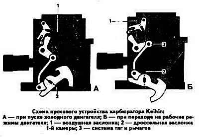
When the engine switches to operating modes, the 3-rod system and lever open the air damper, thus eliminating over-enrichment of the combustible mixture when opening the throttle valve of the 1st chamber.
Idle and transition system
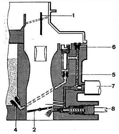
Schematic diagram of the idle system and transition system of the Keihin carburetor: 1 - air damper; 2 - throttle valve 1st chamber; 4 - main fuel jet of the 1st chamber; 5 - idle fuel jet; 6 - idle air jet; 7 - electromagnetic shut-off valve; 8 - adjusting screw for mixture quality (composition).
From the float chamber, fuel is supplied through the main fuel jet 4 of the 1st chamber along the channel to the idle fuel jet 5. At the outlet of the jet 5, the fuel is mixed with air coming out of the vertical channel after the idle air jet 6. The emulsion passes through the channel, the flow section of which is blocked by the electromagnetic shut-off valve 7 at forced idle, and comes out under the throttle valve through the opening adjusted by the screw 8 of the mixture quality (composition).
When the throttle valve is opened before the main metering system of the 1st chamber is switched on, the fuel-air mixture enters the 1st chamber through the bypass channels of the transition system, the slots of which are located above the throttle valve in the closed position, and are made at the level of the hole adjusted by the quality (composition) screw
Main dosing system 1st chamber
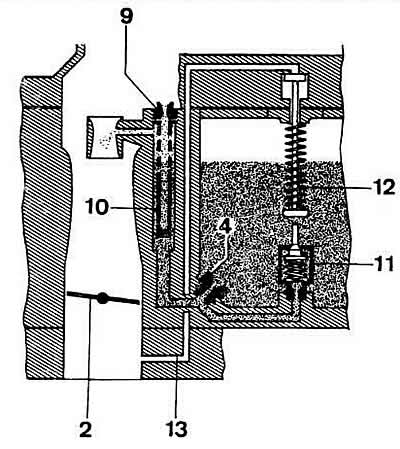
Schematic diagram of the main metering system of the 1st chamber of the Keihin carburetor: 2 - throttle valve; 4 - main fuel jet; 9 - main air jet; 10 - emulsion tube; 11 power mode economizer valve; 12 - economizer valve piston; 13 - vacuum supply channel.
From the float chamber, the fuel enters through the main fuel jet 4 (see diagram) into the emulsion tube 10, in the upper part of which it mixes with air exiting from the opening of the main air jet 9. The fuel-air emulsion is sucked into the small and large diffusers through the horizontal channel. At full engine load, the vacuum in the intake manifold opens the valve 11 of the power mode economizer. The fuel exiting the opening of the valve 11 of the economizer is added to the fuel that passes through the main fuel jet 4, enriching the combustible mixture.
Main dosing system of the 2nd chamber
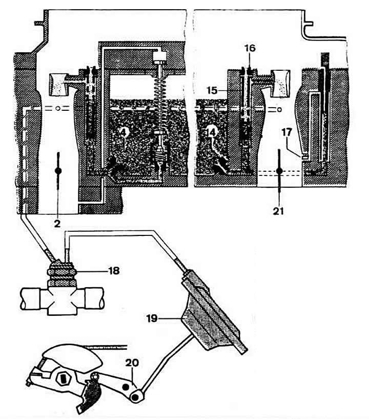
Schematic diagram of the main metering system of the 2nd chamber of the Keihin carburetor: 2 - throttle valve 1st chamber; 4 - main fuel jet of the 1st chamber; 14 - main fuel jet of the 2nd chamber; 15 - Amulsion tube; 16 - main air jet of the 2nd chamber; 17 - slits of the transition system of the 2nd chamber; 18 - thermal pneumatic valve; 15 - pneumatic drive of the throttle valve of the 2nd chamber; 20 - 2nd chamber throttle valve axis; 21 - 2nd chamber throttle valve.
When the throttle valve of the 1st chamber is opened to a certain value, the 2nd chamber is unlocked and the pneumatic drive 19 acts on the throttle valve 21 of the 2nd chamber. The main metering system of the 2nd chamber operates similarly to the main metering system of the 1st chamber. The pneumatic drive of the throttle valve of the 2nd chamber is controlled by the vacuum taken in the area of the carburetor diffusers, the value of which is regulated by the thermo-pneumatic valve 18 included in the engine cooling system.
Accelerator pump
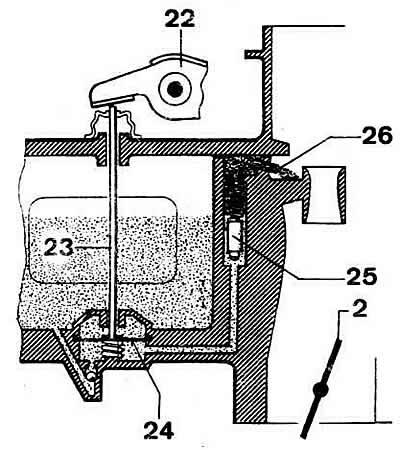
Keihin carburetor accelerator pump diagram: 2 - throttle valve 1st chamber; 22 - pump drive lever; 23 - pump rod; 24 - pump diaphragm; 25 - check valve; 26 - sprayer.
When the throttle valve of the 1st chamber is opened, the cam of the accelerator pump drive, fixed on the axis of the throttle valve of the 1st chamber, acts on the lever 22, which through the rod 23 acts on the diaphragm 24 of the pump. The fuel pumped by the diaphragm is supplied through the channel through the check valve 25 to the atomizer 26.
The damper spring prevents rapid movements of the throttle valve of the 1st chamber, which leads to an increase in the duration of fuel supply by the accelerator pump. After the pump diaphragm returns to its original position, the check valve of the sprayer closes, and the shut-off valve in the float chamber opens and the pump cavity is filled with fuel.
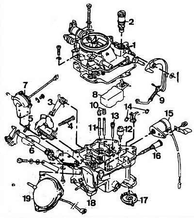
Keihin Carburetor Parts: 1 - carburetor cover; 2 - needle valve; 3 - 2nd chamber throttle control lever; 4 - idle mixture quantity adjusting screw; 5 - limiting screw of the 2nd chamber throttle valve slightly open; 6 - 2nd chamber throttle valve axis; 7 - starting device; 8 - float; 9 - accelerator pump drive lever; 10 - main air jets; 11 - emulsion tubes; 12 - accelerator pump nozzle; 13 - idle fuel jet; 14 - main fuel jets; 15 - electromagnetic shut-off valve; 16 - mixture quality (composition) adjustment screw; 17 - accelerator pump; 18 - carburetor body; 19 - pneumatic drive of the throttle valve of the 2nd chamber.