
Table of contents: Starting device ↓ Idle and transition system ↓ Main dosing system ↓ Accelerator pump ↓
Starting device
When starting a cold engine, under the influence of the thermostatic bimetallic spring of the automatic starting device, the air damper 1 (see diagram) blocks the flow of air through the diffuser, the throttle valve 3, under the influence of the system of rods and cams 2 of the drive, opens slightly, ensuring an increase in the rotation speed of the cold engine at idle.
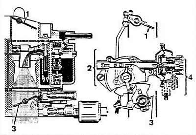
Schemes of operation of the Zenith 2B5 carburetor when starting a cold engine: 1 - air damper; 2 - system of rods and cams for opening the throttle valve; 3 - throttle valve; 4 — pneumatic drive of the air damper.
Under the action of the vacuum in the diaphragm cavity of the starting device, an increased amount of fuel passes through the main fuel jet, which ensures the starting of a cold engine.
After starting the engine, the vacuum that occurs in the intake manifold of the running engine activates the pneumatic actuator 4, which slightly opens the air damper. After warming up with the transition to the load mode, the air damper is slightly opened through a system of rods and levers, driven by the throttle valve, which causes depletion of the combustible mixture and ensures uninterrupted operation of the engine.
Idle and transition system
Fuel taken from the float chamber enters the emulsion tube well through the main fuel jet 5 (see diagram) and is fed to the idle fuel jet 6. At the outlet of jet 6, the fuel is mixed with air entering through the idle air jet. The emulsion is fed to the outlet opening 7 of the idle system under the throttle valve through the opening regulated by the needle screw 8 of the mixture quality (composition), and through the opening closed when the ignition is turned off by the electromagnetic shut-off valve 9.
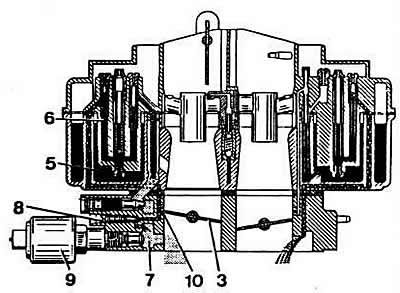
Diagram of the idle system and transition system of the Zenith 2B5 carburetor: 3 — 1st chamber throttle valve; 5 — main fuel jet of the 1st chamber; 6 - idle fuel jet; 7 — idle system outlet; 8 — mixture quality (composition) adjustment screw; 9 - electromagnetic shut-off valve; 10 — transition system gaps.
When the throttle valve 3 is smoothly opened, the combustible mixture enters the vertical channel of the transition system 10, which leads to a gradual increase in the rotation frequency of the engine crankshaft.
The transition system of the 2nd chamber operates similarly, providing an increase in the crankshaft speed as the throttle valve of the 2nd chamber opens. The transition system of the 2nd chamber is not adjustable and does not have a shut-off valve.
Main dosing system
Fuel is supplied to the float chamber 11 (see diagram) via a needle valve. The float, hinged on the axis, regulates the opening of the needle valve to maintain a constant fuel level in the float chamber.
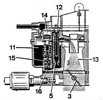
Diagram of the main dosing system of the 1st chamber and economizer of power modes of the Zenith 2B5 carburetor: 3 - throttle valve; 5 - main fuel jet; 11 - float chamber; 12 - main air jet; 13 — diffuser; 14 — power mode economizer; 15 — economizer valve; 16 — fuel supply channel from the economizer.
From the float chamber, the fuel enters the emulsion tube through the main fuel jet 5 of the 1st chamber, where it mixes with air supplied through jet 12. Then the fuel-air mixture fills the mixing chamber formed by the small and large diffusers 13.
The main metering system of the 1st chamber has a power mode economizer. When the vacuum in the area of the throttle valve 3 of the 1st chamber drops, caused by a significant opening of the throttle valve, the vacuum in the diaphragm cavity of the housing of the power mode economizer 14 is removed, the valve 15 of which, under the action of the spring, opens the channel 16 for supplying additional fuel to the fuel jet of the main metering system of the 1st chamber.
The main dosing system of the 2nd chamber operates in a similar manner, except that it does not have a power mode economizer.
Accelerator pump
When the throttle valve 3 (see diagram) of the 1st chamber is opened, the cam 17 actuates the lever 18 of the accelerator pump drive 19 and the pump pumps the fuel sucked into the float chamber into the mixture formation zone through the check valve 20 and the sprayer 21.
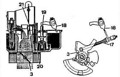
Operation diagram of the accelerator pump of the Zenith 2B5 carburetor: 3 — 1st chamber throttle valve; 17 — accelerator pump drive rod; 18 — accelerator pump drive lever; 19 — accelerator pump piston rod; 20 - check valve; 21 — accelerator pump nozzle.
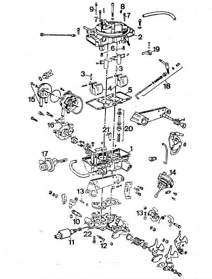
Main parts of the Zenith 2B5 carburetor: 1 - carburetor body; 2 - carburetor cover; 3 - needle valve; 4 - floats; 5 - float chamber gasket; 6 - main fuel jets; 7 - emulsion tubes with fuel and idle air jets; 8 — air jet of the transition system of the 2nd chamber; 9 — air jet of the transition system of the 1st chamber; 10 — idle mixture quantity adjusting screw; 11 - electromagnetic shut-off valve; 12 — adjusting screw for idle mixture quality (composition); 13 — throttle valve limit screw; 14 — pneumatic drive of the throttle valve of the 2nd chamber; 15 - Automatic starting device; 16 - protective cap; 17 — pneumatic drive of the air damper; 18 — accelerator pump drive; 19 — piston rod pusher of the accelerator pump; 20 - accelerator pump; 21 - accelerator pump nozzle; 22 — throttle body.