
Table of contents: Restart protection ↓ Rectilinear motion ↓ Turn left ↓ Description of the power steering… ↓ Principle: Capacitor capacity change… ↓ Used Power Steering J500 ↓
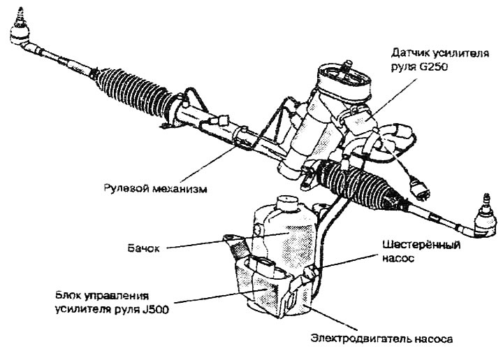
The EPHS power steering is a hydraulic booster with an electric motor drive, which operates depending on the angular velocity of the steering wheel and the speed of the vehicle. The V119 power steering pump unit consists of a gear pump and an electric motor.
Instead of a servo pump (bladed), as with previous amplifiers, a gear pump is used here, combined into a single unit with an electric motor. The gear pump is driven not by the internal combustion engine of the car, but by its own electric motor. The electric motor only works when the ignition is on and the engine of the car is running. The signals of the angular velocity of the steering wheel, the speed of the car and the engine speed are sent to the control unit. This unit regulates the rotation frequency of the anchor of the electric motor/gear pump and, consequently, the pump capacity/amount of pumped liquid.
Restart protection
The electrohydraulic booster has protection against reactivation in case of malfunction, failure or accident. To remove the protection against reactivation, it is necessary to switch off the ignition and start the engine again. If the electric pump unit has overheated, it is necessary to wait approximately 15 minutes for it to cool down. If the protection is not removed despite the elapsed waiting time and restarting the engine, this indicates a malfunction in the on-board network or the electric pump unit. In this case, it is necessary to run self-diagnostics and, if a malfunction is detected, replace the electric motor unit.
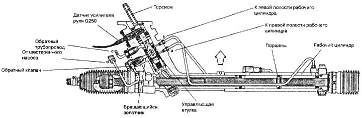
Like a conventional power steering system, the hydraulic control unit has a torsion bar, which is connected to a rotating valve on one side and to a drive gear and control sleeve on the other.
Rectilinear motion
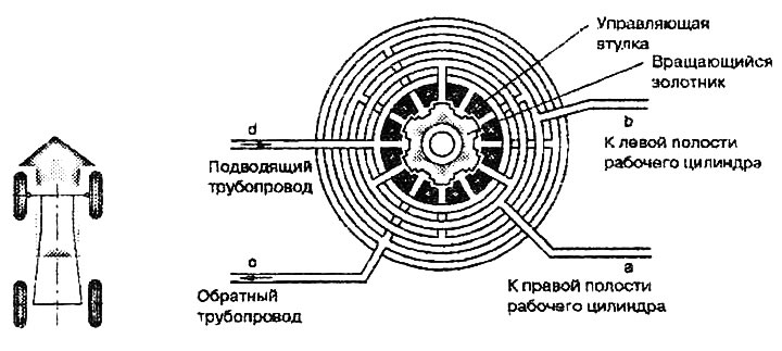
When driving in a straight line, the torsion bar holds the rotating valve and the control sleeve in a neutral position. According to the power steering sensor, the steering wheel does not deviate from the center position. The fluid flows through the hydraulic control unit and through the return pipe into the reservoir with almost no pressure. The grooves of the valve and the control sleeve are in a neutral position relative to each other, so that the fluid enters both cavities of the working cylinder and, accordingly, flows down the return grooves of the control sleeve back into the reservoir.
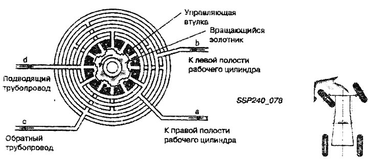
Turn left
Due to the deformation of the torsion bar, the rotating spool valve rotates relative to the control sleeve. The control grooves of the spool valve open the way for oil to enter the right cavity of the working cylinder. Oil under pressure rushes into the working cylinder and helps to turn the steered wheels. At the same time, the spool valve closes the oil supply to the left cavity and opens the drain from it. Under the action of pressure in the right cavity of the working cylinder, oil is squeezed out of the left cavity into the return pipeline. When the steering wheel is turned back to the middle position, the torsion bar returns the spool valve and the control sleeve to the neutral position.
As in the previous system, in the new power steering, the auxiliary force is created by the fluid pressure in the hydraulics. The hydraulic gear pump is driven by an electric motor and therefore does not depend on the car engine. In addition, the degree of amplification now depends on the angle of rotation of the steering wheel.
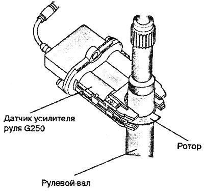
Description of the power steering sensor G250 (capacitive sensor)
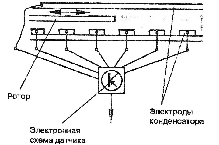
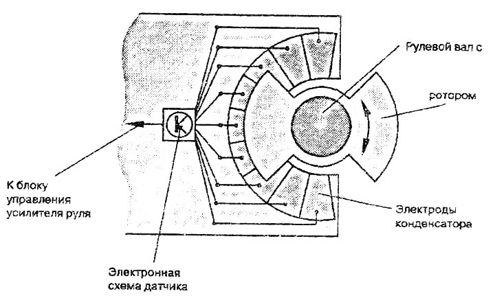
A rotor mounted on the steering shaft rotates between 9 small plate capacitors. Rotation of the rotor causes a change in the capacitance of the capacitors. Based on the change in capacitance, the sensor's electronic circuit calculates signals (steering wheel angle and speed) and transmits them to the power steering control unit.
Principle: Capacitor capacity change circuit
Scheme: top view
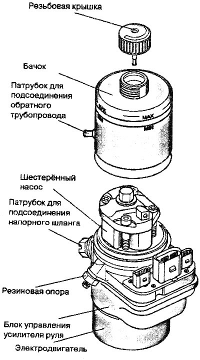
The electric pump unit consists of a hydraulic unit with a gear pump and an electric motor; power steering reservoir; electronics for controlling the electro-hydraulic booster. To check/adjust the fluid level, remove the left headlight. Never pinch the pressure and return lines of the power steering! Pinch the lines will damage their plastic layer. When tying up the pressure and return lines, make sure that their bending radius is at least 100 mm.
Used Power Steering J500
Uses input signals: engine speed from G28; vehicle speeds from G68; steering wheel rotation speed from G250. To control the gear pump drive depending on the steering wheel rotation angle and vehicle speed. Self-diagnosis is performed via the instrument cluster, address word 17. Communication is performed exclusively via the CAN-drive bus. An error message is issued via the instrument cluster control unit.
Pump operation
| Ignition | Car engine | Electric pump | Power steering |
| On | works | works | there is |
| Off | not working, vehicle speed = 0 km/h | does not work | no |
Power steering
| Vehicle speed | Steering wheel angular velocity | Pump performance | Power steering |
| Low, for example when parking | high | high | high ("light" steering wheel) |
| High, for example, on the highway | low | low | low ("tight" steering wheel) |
This article was previously published on the resource AudiManual.ru