
Diesel engine repair 1.4 l car Audi A2

Engine number and characteristics
Engine number The engine number ("engine letter designation" and "current number") is located at the engine-gearbox junction "arrow". Additionally, a sticker...
Engine number The engine number ("engine letter designation" and "current number") is located at the engine-gearbox junction "arrow". Additionally, a sticker...

Removal and installation the engine
Removal Instructions. The engine is removed together with in a downward direction. All cable ties that are removed or cut during dismantling must be...
Removal Instructions. The engine is removed together with in a downward direction. All cable ties that are removed or cut during dismantling must be...

Removal and installation engine mount with engine mount cover
Engine mount with engine mount cover 1. Bolt. Replace, 23 Nm + turn further by + 90° 2. Bolt. Replace, 60 Nm + tighten by + 90° Removal Remove the hood. Remove...
Engine mount with engine mount cover 1. Bolt. Replace, 23 Nm + turn further by + 90° 2. Bolt. Replace, 60 Nm + tighten by + 90° Removal Remove the hood. Remove...

Removal and installation engine mount without engine mount cover
Engine mount without engine mount cover 1. Nut, can be loosened only for engine mount replacement. Replace, 40 Nm + tighten by + 90° 2. Engine bracket 3. Bolt....
Engine mount without engine mount cover 1. Nut, can be loosened only for engine mount replacement. Replace, 40 Nm + tighten by + 90° 2. Engine bracket 3. Bolt....

Removal and installation the pendulum support
Removal Remove the sound insulation of the "arrow". Loosen the arrow bolts and remove the pendulum support. Installation Installation is in reverse order,...
Removal Remove the sound insulation of the "arrow". Loosen the arrow bolts and remove the pendulum support. Installation Installation is in reverse order,...

Poly V-belt drive — design description
Poly V-belt drive: 1. Poly V-belt. Check the degree of wear. Do not bend. Before removing, mark the direction of rotation with chalk or a felt-tip pen....
Poly V-belt drive: 1. Poly V-belt. Check the degree of wear. Do not bend. Before removing, mark the direction of rotation with chalk or a felt-tip pen....

Removal and installation a poly V-belt
Removal Remove sound insulation. Instructions. Mark the direction of rotation of the poly V-belt with chalk or a felt-tip pen. Installing a belt that has...
Removal Remove sound insulation. Instructions. Mark the direction of rotation of the poly V-belt with chalk or a felt-tip pen. Installing a belt that has...

Removal and installation the torsional vibration damper
Removal Remove the poly V-belt. Unscrew the torsional vibration damper; to do this, hold the crankshaft by the central bolt with a spanner. Installation...
Removal Remove the poly V-belt. Unscrew the torsional vibration damper; to do this, hold the crankshaft by the central bolt with a spanner. Installation...

Removal and installation the auxiliary unit bracket
Removal Remove the poly V-belt. Caution! Do not open the air conditioning system circuit of the air conditioning system. To avoid damage to the air...
Removal Remove the poly V-belt. Caution! Do not open the air conditioning system circuit of the air conditioning system. To avoid damage to the air...

Sealing flanges and dual mass flywheel
Sealing flanges and dual mass flywheel: 1. Sealing cuff, replace, do not lubricate with oil 2. The sealing flange on the belt pulley side must be installed on...
Sealing flanges and dual mass flywheel: 1. Sealing cuff, replace, do not lubricate with oil 2. The sealing flange on the belt pulley side must be installed on...

Replacing the crankshaft seal on the belt pulley side
The engine is installed. Remove the toothed belt: toothed belt drive with hydraulically damped tension roller, toothed belt drive with friction-damped tension...
The engine is installed. Remove the toothed belt: toothed belt drive with hydraulically damped tension roller, toothed belt drive with friction-damped tension...

Removal and installation the sealing flange on the belt pulley side
Removal The engine is installed. Unscrew the air guide pipe bracket from the oil pan "arrows". Remove the right air duct hose "2" from the intercooler. Ignore...
Removal The engine is installed. Unscrew the air guide pipe bracket from the oil pan "arrows". Remove the right air duct hose "2" from the intercooler. Ignore...

Removal and installation a dual mass flywheel
Removal The engine or gearbox is removed. Remove the clutch basket. Mark the position of the dual mass flywheel relative to the crankshaft. Instructions: In...
Removal The engine or gearbox is removed. Remove the clutch basket. Mark the position of the dual mass flywheel relative to the crankshaft. Instructions: In...

Removal and installation the sealing flange from the gearbox side
Removal Gearbox removed. Remove dual mass flywheel. Remove intermediate sheet of sealing flange and centering bushings "arrows". Loosen bolts "1...8". Remove...
Removal Gearbox removed. Remove dual mass flywheel. Remove intermediate sheet of sealing flange and centering bushings "arrows". Loosen bolts "1...8". Remove...

Balance shaft and crankshaft frame — design description
Instructions: Lubricate all supporting and working surfaces with oil. Balance shaft and crankshaft frame: 1. Chain. Observe the installation position 2. Bolt....
Instructions: Lubricate all supporting and working surfaces with oil. Balance shaft and crankshaft frame: 1. Chain. Observe the installation position 2. Bolt....

Removal and installation the balance shaft and crankshaft frame
Removal Remove the poly V-belt. Remove the toothed belt: toothed belt drive with hydraulically damped tension roller, toothed belt drive with friction-damped...
Removal Remove the poly V-belt. Remove the toothed belt: toothed belt drive with hydraulically damped tension roller, toothed belt drive with friction-damped...

Crankshaft — design description
Instructions: Lubricate all supporting and working surfaces with oil. Crankshaft: 1. Bearing insert 1, 2, and 4 for cover without lubrication groove, for...
Instructions: Lubricate all supporting and working surfaces with oil. Crankshaft: 1. Bearing insert 1, 2, and 4 for cover without lubrication groove, for...

Removal and installation the crankshaft sprocket
Be sure to replace sprocket "2" every time the bolts are loosened. Instructions. After the second tightening of the sprocket, the contact points of the...
Be sure to replace sprocket "2" every time the bolts are loosened. Instructions. After the second tightening of the sprocket, the contact points of the...

Checking the protrusion of the dowel pin from the crankshaft
1. Asterisk 2. Bolt 3. The protrusion of the installation pin "3" from the crankshaft. Dimension "a" = 2.5...3.0 mm. Check the protrusion "a" of the mounting...
1. Asterisk 2. Bolt 3. The protrusion of the installation pin "3" from the crankshaft. Dimension "a" = 2.5...3.0 mm. Check the protrusion "a" of the mounting...

Removal and installation the drive sprocket of the chain drive
Removal Remove the oil pan. Remove the sealing flange from the belt pulley side. Remove the oil pump sprocket, chain tensioner and chain. Remove the crankshaft...
Removal Remove the oil pan. Remove the sealing flange from the belt pulley side. Remove the oil pump sprocket, chain tensioner and chain. Remove the crankshaft...

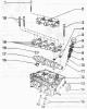
Cylinder head — design description
Cylinder head: 1. Upper part of the belt guard 2. Toothed belt 3. Bolt, 10 Nm 4. Bolt, 25 Nm 5. Bolt, 100 Nm 6. Camshaft drive sprocket 7. Bushing 8. Rear part...
Cylinder head: 1. Upper part of the belt guard 2. Toothed belt 3. Bolt, 10 Nm 4. Bolt, 25 Nm 5. Bolt, 100 Nm 6. Camshaft drive sprocket 7. Bushing 8. Rear part...

Removal and installation the cylinder head cover
Removal Remove the hood. If present, loosen the bracket. Remove the engine cover "arrows". Remove the sound insulation underneath. Lift the caps "3 and 4" of...
Removal Remove the hood. If present, loosen the bracket. Remove the engine cover "arrows". Remove the sound insulation underneath. Lift the caps "3 and 4" of...

Removal and installation of the cylinder head
Removal Observe safety precautions when disconnecting the battery. The battery is located in a hidden niche of the trunk. Turn off the ignition and remove the...
Removal Observe safety precautions when disconnecting the battery. The battery is located in a hidden niche of the trunk. Turn off the ignition and remove the...

Checking the compression in the cylinders
Oil temperature not less than 30°C. Battery voltage minimum 12.5 V. Remove the hood. If available, unfasten the bracket. Remove the engine cover "arrows"....
Oil temperature not less than 30°C. Battery voltage minimum 12.5 V. Remove the hood. If available, unfasten the bracket. Remove the engine cover "arrows"....

Toothed belt drive with hydraulically damped tension roller
Toothed belt drive with hydraulically damped tension roller: 1. Upper part of the belt guard 2. Toothed belt. Check the degree of wear, before removing, mark...
Toothed belt drive with hydraulically damped tension roller: 1. Upper part of the belt guard 2. Toothed belt. Check the degree of wear, before removing, mark...

Removal and installation a toothed belt with a hydraulically damped tension roller
Removal Remove the right front wheel. Remove the sound insulation. Remove the poly V-belt. Remove the hood. If available, unfasten the bracket. Remove the...
Removal Remove the right front wheel. Remove the sound insulation. Remove the poly V-belt. Remove the hood. If available, unfasten the bracket. Remove the...

Toothed belt drive with friction damped tension roller
Toothed belt drive with friction damped tension roller: 1. Bolt. Replace, 10 Nm + tighten by +90° 2. Torsional vibration damper with pulley for poly V-belt,...
Toothed belt drive with friction damped tension roller: 1. Bolt. Replace, 10 Nm + tighten by +90° 2. Torsional vibration damper with pulley for poly V-belt,...

Removal and installation a toothed belt with a friction-damped tension roller
Removal Remove the right front wheel. Remove the sound insulation. Remove the poly V-belt. Remove the hood. If present, loosen the bracket. Remove the engine...
Removal Remove the right front wheel. Remove the sound insulation. Remove the poly V-belt. Remove the hood. If present, loosen the bracket. Remove the engine...
Valve mechanism — design description
Instructions. After installing the camshaft, the engine must not be started for approximately 30 minutes. The hydraulic tappets must be settled (otherwise the...
Instructions. After installing the camshaft, the engine must not be started for approximately 30 minutes. The hydraulic tappets must be settled (otherwise the...

Checking the axial clearance of the camshaft
Take the measurement with the tappets removed and the bearing caps installed. Attach the universal stand "VW 387" with the dial indicator "VAS 6079" to the...
Take the measurement with the tappets removed and the bearing caps installed. Attach the universal stand "VW 387" with the dial indicator "VAS 6079" to the...

Replacing the camshaft seal
The cylinder head is installed. Remove the toothed belt: toothed belt drive with hydraulically damped tension roller, toothed belt drive with friction-damped...
The cylinder head is installed. Remove the toothed belt: toothed belt drive with hydraulically damped tension roller, toothed belt drive with friction-damped...

Removal and installation the camshaft
Removal The cylinder head is installed. Remove the toothed belt, toothed belt drive with hydraulically damped tension roller, toothed belt drive with...
Removal The cylinder head is installed. Remove the toothed belt, toothed belt drive with hydraulically damped tension roller, toothed belt drive with...

Checking hydraulic tappets
Instructions. Hydraulic tappets cannot be repaired. Irregular noises in the valve mechanism when starting the engine are acceptable. Start the engine and leave...
Instructions. Hydraulic tappets cannot be repaired. Irregular noises in the valve mechanism when starting the engine are acceptable. Start the engine and leave...

Replacing valve stem seals
The cylinder head is installed. With the cylinder head removed, the valve stem seals can be replaced using the valve spring puller "2037". Remove the camshaft....
The cylinder head is installed. With the cylinder head removed, the valve stem seals can be replaced using the valve spring puller "2037". Remove the camshaft....

Valve sizes
Size Inlet valve Exhaust valve a, mm 35,95 31,45 b, mm 6,980 6,956 c, mm 89,95 89,95 α 45 45 Instructions. Valves may not be modified. Only lapping is...
Size Inlet valve Exhaust valve a, mm 35,95 31,45 b, mm 6,980 6,956 c, mm 89,95 89,95 α 45 45 Instructions. Valves may not be modified. Only lapping is...

Checking the valve guides
Insert the valve into the guide. The end of the valve stem should overlap the guide. Determine the clearance by rocking. Wear limit: 1.3 mm. Instructions. If...
Insert the valve into the guide. The end of the valve stem should overlap the guide. Determine the clearance by rocking. Wear limit: 1.3 mm. Instructions. If...

Modification of valve seats
If the required quality of the valve seat contact belt is not achieved during grinding, the seat must be reworked. Instructions. When repairing engines with...
If the required quality of the valve seat contact belt is not achieved during grinding, the seat must be reworked. Instructions. When repairing engines with...
This section is available on russian, bulgarian, belarusian, ukrainian, serbian, croatian, romanian, polish, slovak, hungarian
Similar sections of other Audi car models:
Power unit: Engine Audi 80 B4 (1991-1996)
Power unit: Engine removed Audi 100 C3 (1982-1990, diesel)
Power unit: Engine repair Audi A3 Type 8L (1996-2003)
Power unit: Engine repair Audi A4 B5 (1994-2001, petrol)
Power unit: Engine repair Audi A6 C5 (1997-2004)
Power unit: Engine Audi 80 B4 (1991-1996)
Power unit: Engine removed Audi 100 C3 (1982-1990, diesel)
Power unit: Engine repair Audi A3 Type 8L (1996-2003)
Power unit: Engine repair Audi A4 B5 (1994-2001, petrol)
Power unit: Engine repair Audi A6 C5 (1997-2004)
Share information:
- General information
- Introduction to the guide
- Maintenance
- Engine 1.4 l (gasoline)
- Engine repair
- Lubrication system
- Cooling system
- Exhaust system
- Engine 1.6 l (gasoline)
- Engine repair
- Lubrication system
- Cooling system
- Exhaust system
- Engine 1.2 l (diesel)
- Engine repair
- Lubrication system
- Cooling system
- Injection and turbocharging
- Engine 1.4 l (diesel)
- Engine repair
- Lubrication system
- Cooling system
- Turbocharging system
- Supply system
- Fuel injection system
- Exhaust system
- Transmission
- Mechanical gearbox 02J
- Mechanical gearbox 02T
- Mechanical gearbox 085 DS
- Chassis
- Car suspension
- Steering
- Brake system
- Body
- Exterior
- Interior
- Seats
- Doors, locks and windows
- Safety system
- Heating and air conditioning
- Electrical equipment
- Power devices
- Equipment and devices
- Wipers and washers
- Lighting and lamps
- Breakers and switches
- Electrical circuits