
Table of contents: Removal ↓ Disconnecting the engine and gearbox ↓ Engine installation ↓ Engine/Gearbox Mounting ↓
Removal
Instructions. The engine is removed together with in a downward direction. All cable ties that are removed or cut during dismantling must be reinstalled in the same places during installation. The battery is located in a hidden niche in the trunk.
Turn off the ignition and remove the key from the ignition switch.
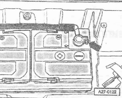
Disconnect the ground wire "arrow" from the battery. Remove the hood.
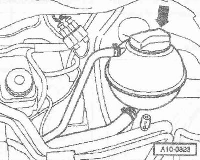
Attention! When opening the coolant can, hot steam or hot coolant may come out, cover the lid with a rag and carefully open it.
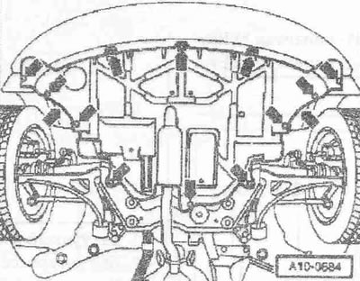
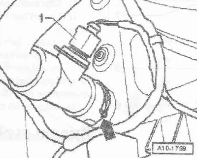
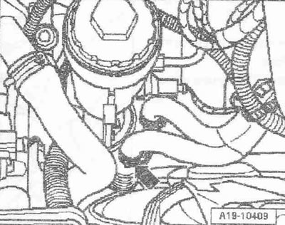
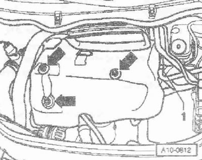
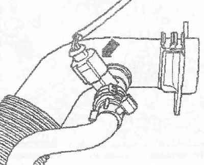
Open the "arrow" cap of the expansion tank. Remove the front wheels. Remove the "arrow" sound insulation. Place a tray for the "VAS 6208" service cranes under the engine. Disconnect the plug "1" of the coolant temperature gauge sensor at the radiator outlet "G83". Remove the lower coolant supply hose "arrow" from the radiator and drain the coolant.
Remove the coolant supply hose "arrow" from the oil radiator, lower it down and drain the remaining coolant.
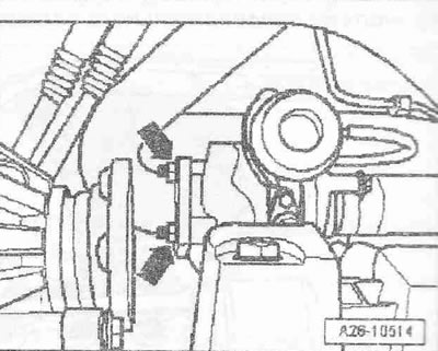
Loosen all the nuts of the "arrow" threaded connections of the exhaust system to the turbocharger.
Instructions: The detachable element must not be bent more than 10°. Risk of damage!
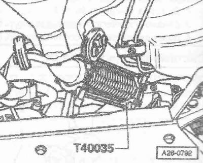
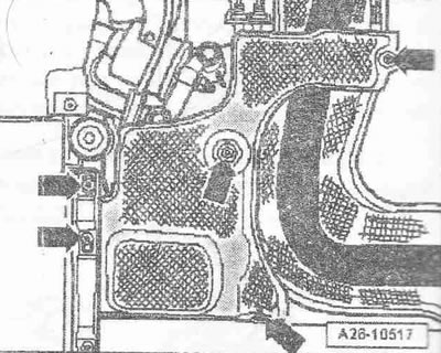
Support the detachable element with the "T40035" retainer. Unscrew the heat shield of the exhaust system "arrows".
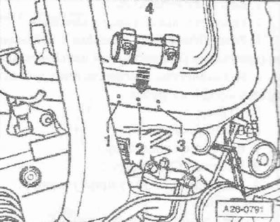
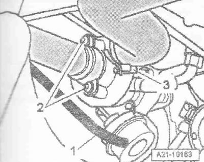
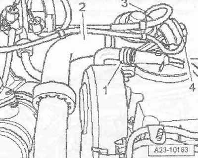
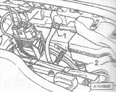
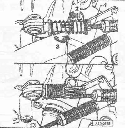
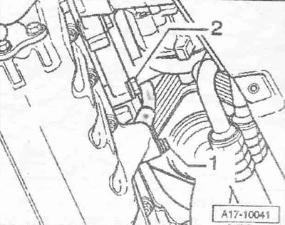
On vehicles with a detachable exhaust system, loosen the nuts of the fastening sleeve "4" and move the fastening sleeve back to disconnect the exhaust system.
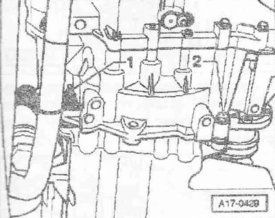
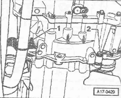
On vehicles with a non-detachable exhaust system, cut the exhaust pipe at a right angle at connector "2" using the VAS 6254 chain pipe cutter. Ignore items "1" and "3".
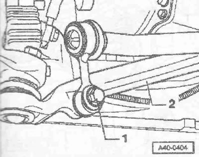
Loosen bolt "1" of suspension arm strut "2".
Unscrew the heat shield of the left drive shaft "arrow". Unscrew the left drive shaft from the shaft with the gearbox flange and hang it up. Remove the right drive shaft.
Vehicles with letter designation AMF
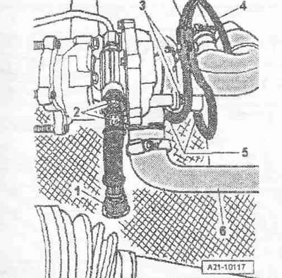
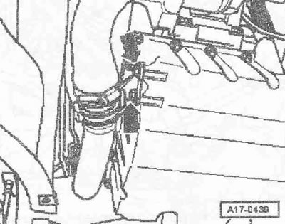
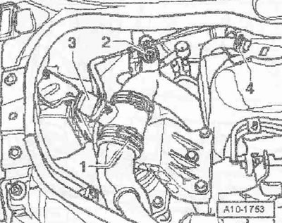
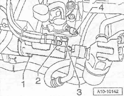
Disconnect the air duct hose "6" from the turbocharger. Disconnect the hoses "5" of the boost pressure control system from the turbocharger and the boost pressure control pneumatic power element. Disconnect the ventilation hose "4". Unscrew the bolts "3" and remove the air guide pipe from the turbocharger.
Instructions. The air guide pipe remains in the installation position and is removed later in the upward direction. Pos. "1" and "2" are not to be taken into account.
Cars with the letter designation ATL, BHC
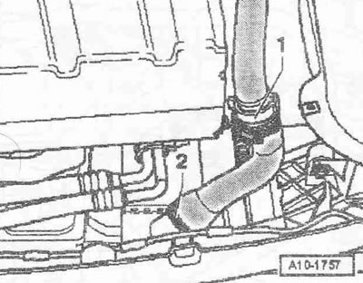
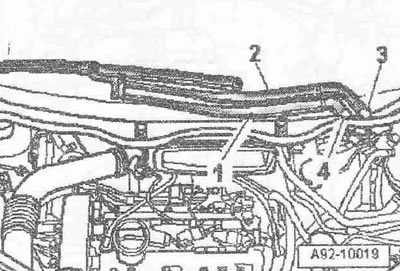
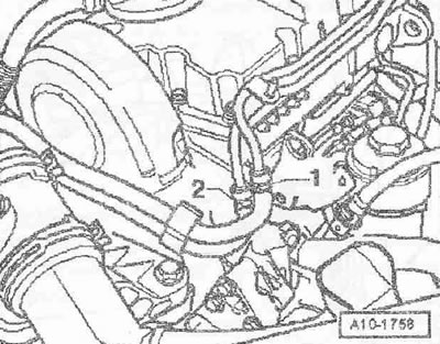
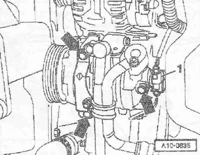
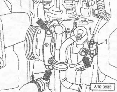
Remove the vacuum hose "1" of the boost pressure control power vacuum pneumatic element and put it aside. Unscrew the bolts "2" and remove the air guide pipe from the turbocharger. Disconnect the air duct hose "3" from the turbocharger.
Instructions: The air guide pipe remains in the installation position and is removed later in an upward direction.
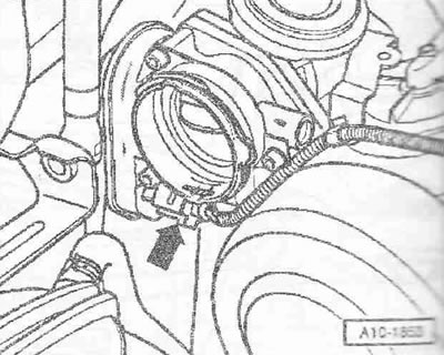
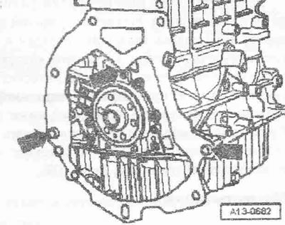
The air guide pipe bracket has been unscrewed from the "arrow" oil pan.
Remove the right air duct hose "2" of the intercooler. Ignore pos. "1". Disconnect the plug connector "arrow" of the oil level and temperature sensor "G266". Unfasten the electrical wiring.
Instructions. Depending on the version, the oil level and temperature sensor "G266" can be located at the front of the oil pan.
If present, loosen the bracket. Remove the "arrow" engine cover. Remove the noise insulation underneath.
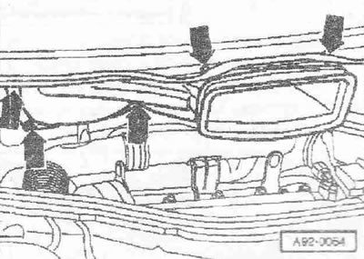
Lift the caps "3 and 4" of both parts of the windshield wiper arm with a screwdriver. Loosen the nuts of both parts of the windshield wiper arm with a few turns. Loosen the fit of the arms "1 and 2" of the windshield wiper blades on the axles one by one with light rocking movements. Completely unscrew the nuts and remove both parts of the windshield wiper arm.
Instructions: If it is not possible to remove the lever in this way, then in this case it is necessary to use a standard puller.
Disconnect the washer fluid supply pipe "3". If present, disconnect the plug connectors "4 and 5" of the heated windshield washer nozzles. Loosen the hose clamp "6" using hose clamp pliers "V.A.G 1921" and remove the drain hose from the deflector grille. Remove the rubber seal "1" of the deflector grille. Remove the deflector grille "2".
Loosen the nuts and bolts of the "arrow". Pull the fresh air supply duct forward and remove it, turning it to the right side of the car.
Vehicles with letter designation AMF
Disconnect the air-water hose "2" from the mechanical EGR valve. Disconnect the vacuum hose "3" of the mechanical EGR valve. Disconnect the vacuum hose "4" of the power vacuum pneumatic element of the intake manifold flap. Ignore pos. "1".
Remove the air duct hose "2" from the intercooler.
Vehicles with the letter designation ATL
Shine the air duct hose "3" from the electric motor of the intake manifold flap "VI57" for this slightly loosen the clamp "2". Disconnect the vacuum hose "1" of the mechanical EGR valve.
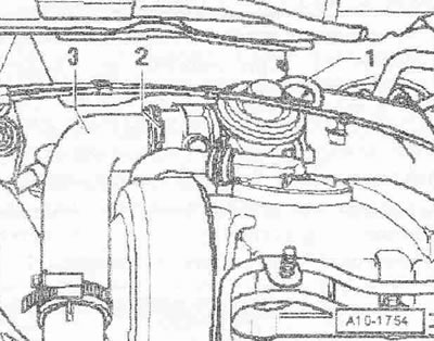
Remove the air duct hose "2" from the intercooler. Disconnect the plug connector of the boost pressure sensor "G31" pos. "1".
Warning! Risk of burns from contact with fuel lines or fuel heated to 100°C. Wait until the fuel has cooled before opening the fuel line connections.
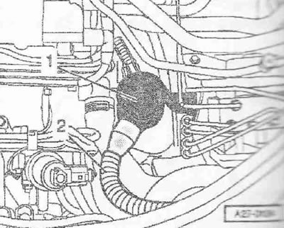
Mark and disconnect the fuel pre-supply line "2" and the fuel return line "1". Unfasten the fuel lines.
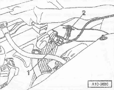
Disconnect the air duct hose "1" from the air flow meter "G70". Disconnect the plug connector "3" of the air flow meter "G70". Unscrew the nut "2". Remove the crankcase ventilation hose "4" from the cylinder head cover. Pull out the air guide pipe together with the air flow meter "G70".
If available, disconnect the "arrow" plug connector of the crankcase ventilation heating coil "N79". Remove the air guide pipe.
Vehicles with the letter designation ATL
Disconnect the "arrow" plug connector of the intake manifold flap motor "VI57". Loosen the wiring.
Remove the dipstick from the guide tube. Remove the dipstick guide tube "1". Remove the oil filler tube "2" from the oil filler tank.
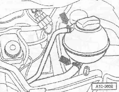
Remove the drain hose "2". Remove the water intake tank "1".
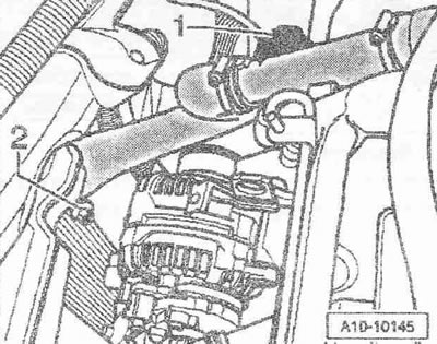
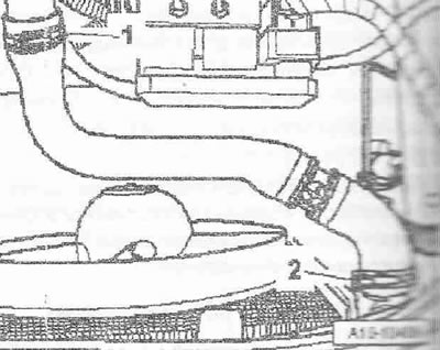
Remove the left upper coolant supply hose "pos. 1 and 2".
Remove the engine coolant supply hose "arrow" from the front connecting fitting.
Pull the coolant supply hose out of bracket "1" and remove it. Ignore item "2".
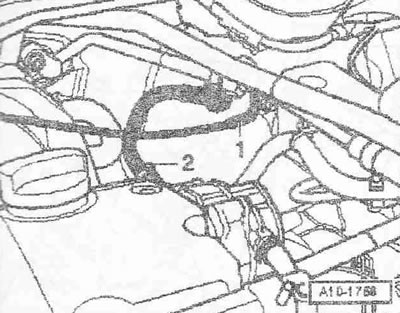
Mark the coolant pre-supply hose "1" and coolant return hose "2" to the heater heat exchanger and remove the coolant hoses on the front panel.
Cars with the letter designation ATL, BHC
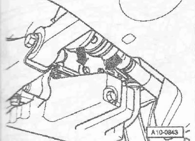
Disconnect vacuum hose "1".
Remove vacuum hose "2" from tandem pump to brake booster. Unfasten vacuum hoses.
Remove the coolant supply hoses from the expansion tank "arrows" and unfasten the upper coolant supply hose.
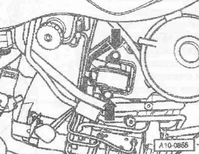
Open the cable clamp "2" and remove the casing "3" from the pull-in relay "1" in an upward direction.
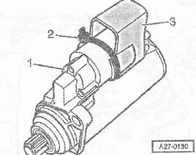
Disconnect the plug connector "4" of the reverse light switch "F4". Unfasten the electrical wiring. Disconnect the plug connector of terminal 50 "pos. 3" of the starter solenoid relay. Unscrew the nut "2" and remove the B+ wire. Unscrew the nut "1" and remove the ground wire.
Disconnect the plug connector "1" of the electromagnetic clutch of the air conditioner compressor. Ignore the "arrows".
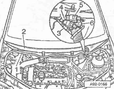
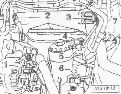
Disconnect the plug connector of the D+ terminal "pos. 1" of the generator. Disconnect the plug connectors "2" of the glow plugs. Pull out the release pin and unscrew the knurled nut "3" of the central connector of the pump-injector modules.
Disconnect the plug connector of the Hall sensor "G40" item "4" and the engine speed sensor "G28" item "5". Disconnect the plug connector "6" of the oil pressure sensor "F1". Disconnect the plug connector "7" of the fuel temperature sensor "G81".
Disconnect the "arrow" connector of the coolant temperature gauge sensor "G62".
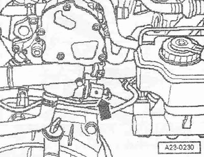
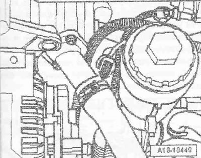
Unscrew the electrical wiring harness bracket from the coolant supply nipple "arrow". Unfasten the electrical wiring harness to the engine.
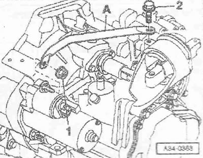
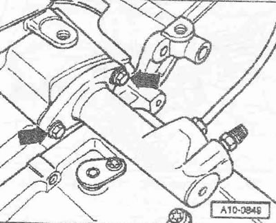
Remove the cross support "A" by unscrewing the nut "1" and bolt "2".
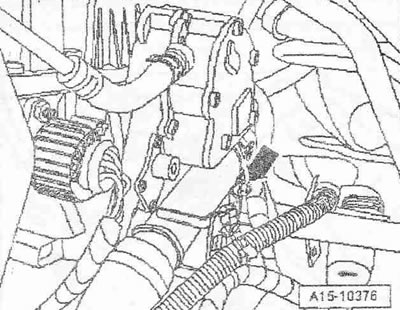
Unscrew the "arrow" cable operator from the gearbox.
Caution! The cable retainers must not be removed with the shift shaft lever or the intermediate lever. If the cable retainers have been removed, they must be replaced.
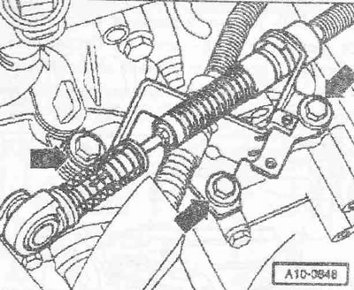
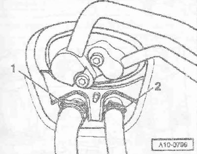
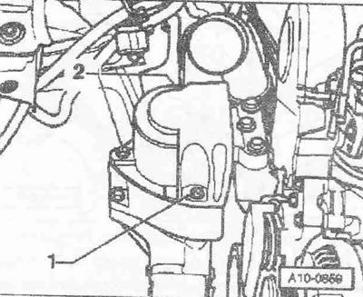
Unlock the gear selection and shift cable lock by pushing the movable sleeve all the way in "in the direction of the arrow" and then locking it by turning it to the left "in the direction of arrow 3". Pull the cables "1" out of the cable lock.
Unscrew the "arrow" bolts. Remove the line bracket and move the clutch slave cylinder to the side; do not disconnect the pipelines.
Caution! After removing the clutch slave cylinder, do not press the clutch pedal any more. Use the "VAS 5085" stepladder to unscrew the bolts of the fastening elements.
Car with engine mount cover
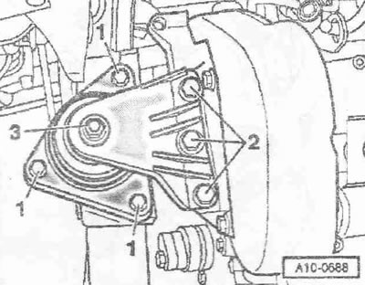
Remove the engine mount cover by unscrewing bolts "1 and 2".
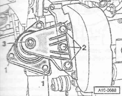
Loosen bolts "1 and 3" by approximately 2 turns. Ignore item "2".
Cars without engine mount cover
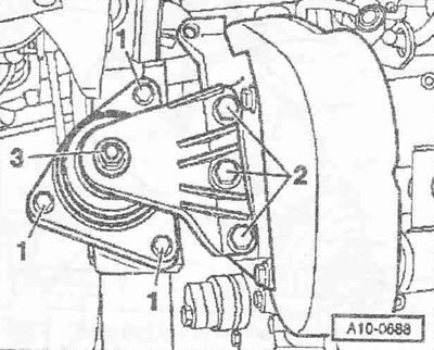
Loosen bolts "1 and 2" by about 2 turns. Nut "3" can be loosened only for replacing the engine mount.
Loosen the gearbox support arrow bolts by approximately 2 turns.
Instructions. Mark the direction of rotation of the poly V-belt with chalk or a felt-tip pen. Installing a belt that has already been used in the opposite direction of rotation may result in its destruction.
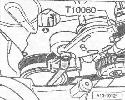
To loosen the poly V-belt, turn the belt loosening device with a spanner "in the direction of the arrow". Fix the belt tensioner by inserting the "T10060 A" lock into the fixing holes. Remove the poly V-belt.
Caution! Do not open the air conditioning system circuit of the air conditioning system. To avoid damage to the air conditioning compressor, as well as the pipes and hoses of the air conditioning system circuit, ensure that the lines and hoses are laid without tension, kinks or breaks.
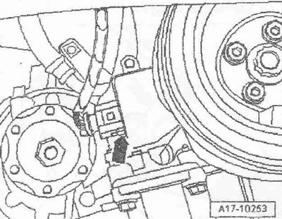
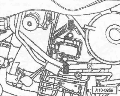
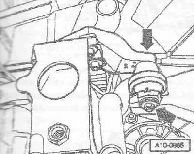
Loosen the air conditioner compressor "arrow" bolts. Hang the air conditioner compressor to the radiator frame. Ignore pos. "1".
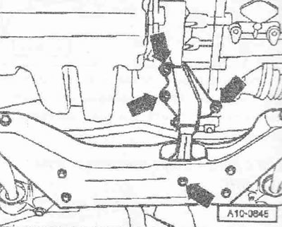
Loosen the arrow bolts and remove the pendulum support.
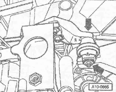
Unscrew screw "2". Ignore item "1".
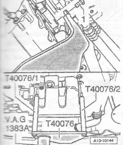
Unscrew screw "2". Screw engine holder "T40076" with bolt "1" to the cylinder block with a torque of approximately 20 Nm. Insert engine holder bolts "T40076" into the cylinder block and secure bolt "T40076/2" for this tighten the nut with a torque of approximately 20 Nm. Insert engine and gearbox lift "VAG 1383 A" into the engine holder. Raise the engine together with the gearbox slightly. Use stepladder "VAS 5085" to unscrew the mounting bolts.
Car with engine mount cover
Unscrew bolts "1 and 3" and remove the bracket with engine mount "2".
Cars without engine mount cover
Nut "3" can be loosened only to replace the engine mount. Unscrew bolts "1 and 3" and remove the bracket with the engine mount.
Loosen the "arrow" bolts on the gearbox support.
Instructions. Check that all hoses and wires between the engine, gearbox and body are disconnected. Lower the engine with the gearbox carefully to avoid damage. Ensure free access to the air conditioning compressor or to the area between the drive shaft and turbocharger.
Lower the engine together with the gearbox slowly using the engine and gearbox lift "VAG 1383 A".
Disconnecting the engine and gearbox
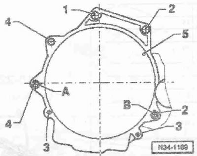
The engine together with the gearbox is removed and installed on the engine holder "T40076". Unscrew the bolts "1...5" connecting the engine to the gearbox. Remove the starter. Move the gearbox away from the engine.
Engine installation
The engine is mounted on the T40076 engine mount. Installation is in the reverse order, while it is necessary to take into account: during installation, replace the self-locking nuts and bolts. Replace the bolts tightened to a certain angle, as well as the cuffs and seals. The hoses and hose nipples of the supercharger system must be cleaned of oils and grease before installation. Do not use lubricants under any circumstances. Use clamps of the appropriate series to secure all hose connections. During assembly, install all cable clamps in their original places. Clean the splines of the gearbox input shaft and the splines of the bushings of the clutch discs that have already worked, remove corrosion and apply a thin layer of grease for splined joints of clutch discs to the splines. Do not lubricate the guide sleeve. Check the centering of the driven disc of the clutch. Check the release bearing of the clutch for wear, replace if necessary. Check the cylinder block for the presence of centering bushings for centering the engine and gearbox; insert the bushings if necessary. Make sure that the intermediate sheet is installed on the sealing flange and is inserted into the centering bushings "arrows". Bolt the gearbox to the engine.
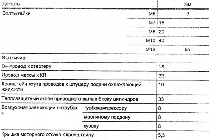
Instructions. The tightening torques given are valid for lightly lubricated, phosphated or oxidized nuts and bolts. It is permissible to use additional lubricants, such as motor or transmission oils, except for graphite-containing ones. Do not use degreased parts. The tolerance of tightening torques is ±15%.
Engine/Gearbox Mounting
| 1 1), 2 | M12x55 | 80 |
| 3 | M10x50 | 40 |
| 41)2) | N112x150 | 80 |
| 53) | N16x12 | 10 |
| A, B | Centering bushings | |
1) Bolt with threaded pin M8.
2) Additionally for the starter to the gearbox.
3) Protective sheet for dual mass flywheel.
Start the engine together with the gearbox into the engine compartment of the body. First tighten bolts "1 and 2" of the fastening elements on the engine by hand. Ignore pos. "03".
First, tighten the bolts "arrows" of the fastening elements on the gearbox by hand. Use new bolts for fastening. Remove the engine holder "T40076" from the engine. Install the drive shafts. Install the ball joint. Install the catalytic converter. Install the pendulum support. Install the air conditioning compressor. Install the starter. Install the poly V-belt.

Before installing the clutch slave cylinder, do not press the clutch pedal. Install the clutch slave cylinder. Install the gearshift drive in the gearbox and adjust it. Install the cross support. Install the air ducts in the clamps. Install the fastening elements without mechanical stress. Electrical connectors and their gaskets. Observe safety precautions after connecting the battery. Install the windshield wiper arm. Check the oil level. Do not use the charger to help start the car. There is a risk of damaging the vehicle controls. Add coolant.
Tightening torques
This article was copied from an online resource AudiManual