
Removal
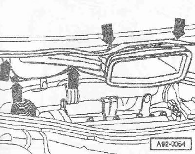
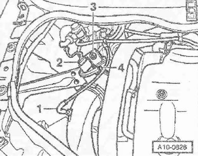
Remove the right front wheel. Remove the sound insulation. Remove the poly V-belt. Remove the hood. If present, loosen the bracket. Remove the engine cover "arrows". Remove the sound insulation underneath. Use a screwdriver to lift the caps "3 and 4" of both parts of the windshield wiper arm. Loosen the nuts of both parts of the windshield wiper arm with a few turns. Loosen the arms "1 and 2" of the windshield wipers on the axles one by one by lightly rocking them. Completely unscrew the nuts and remove both parts of the windshield wiper arm. If it is impossible to remove the arm in this way, then in this case it is necessary to use a standard puller.
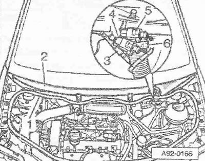
Disconnect the washer fluid supply pipe "3". If present, disconnect the plug connectors "4 and 5" of the heated windshield washer sprayers. Loosen the hose clamp "6" using hose clamps "V.A.G 1921" and remove the drain hose from the deflector grille. Remove the rubber seal "1" of the deflector grille. Remove the deflector grille "2". Unfasten the washer fluid supply pipe.
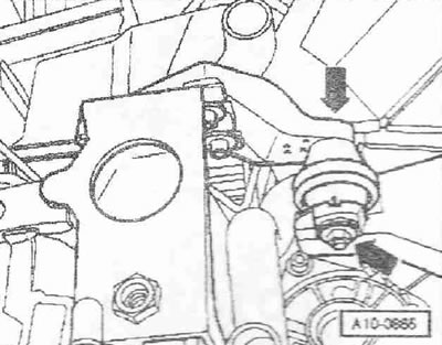
Loosen the nuts and bolts of the "arrow". Pull the fresh air supply duct forward and remove it, turning it to the right side of the car.
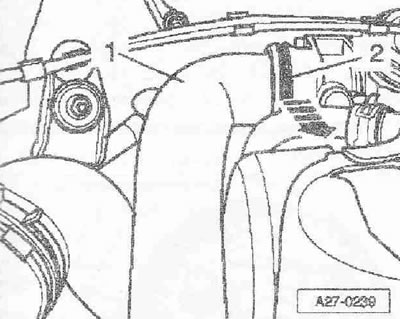
Remove the air duct hose "1" from the suction pipe, to do this, release the clamps (where available) "2" "arrow".
Vehicles with the letter designation AMF, VNS
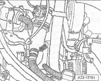
Remove the resonator from the air guide pipe "arrow".
All cars
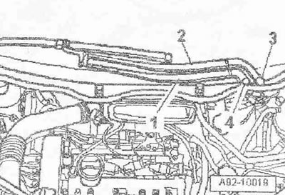
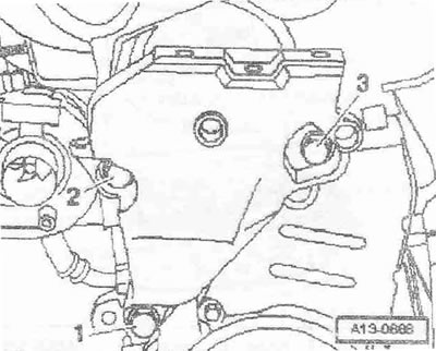
Disconnect plug connector "2" of air flow meter "G70". Remove vacuum hose "1". Loosen hose clamp "4" and remove air guide pipe together with air flow meter "G70". Ignore item "3".
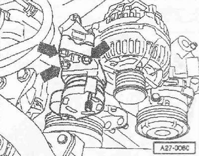
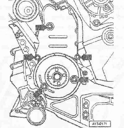
Unscrew the tensioner of the poly V-belt "arrows". Remove the upper part of the protective cover of the belt "arrows".
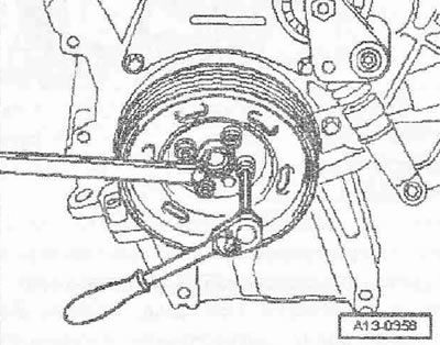
Loosen the torsional vibration damper by holding the crankshaft with a spanner by the central bolt.
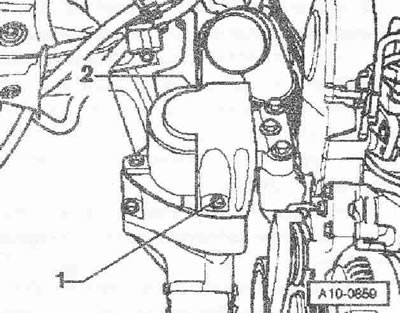
Unscrew the central and lower parts of the belt protective cover "arrows".
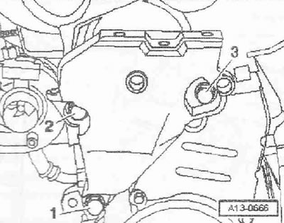
Unscrew the lower bolt "1" of the engine support. Bolts "2" and "3" are unscrewed later.
Install the crossmember "10.222 A" with adapters "10.222 A/13" and adapter "T40093/6" on the edges of the bolted joints of the wings.
Caution! Insert the adapter "10. 222 A/13" into the hood catches "arrow".
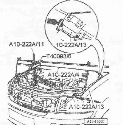
The clamping bolt in the adapter "T40093/6" must be unscrewed. The adapter "T40093/6" is installed so that its bracket faces upward. Hook the hook of the lead screw carabiner "10.222 A/11" to the engine eye. Tighten the engine with the lead screw without lifting it.
Car with engine mount cover
Remove the engine mount cover by unscrewing bolts "1 and 2".
Unscrew bolts "1 and 3" and remove the bracket with engine mount "2".
Cars without engine mount cover
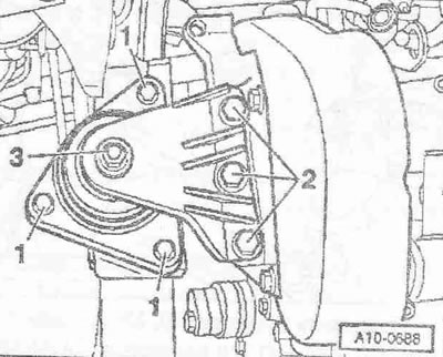
Nut "3" can be loosened only to replace the engine mount. Unscrew bolts "1 and 2" and remove the bracket with the engine mount.
All cars
Unscrew the upper bolts "2" and "3" and remove the engine support. Ignore pos. "1".
Caution! The engine may only be turned by the crankshaft in the direction of its rotation (clockwise). To rotate the engine shaft, install the center bolt on the crankshaft.
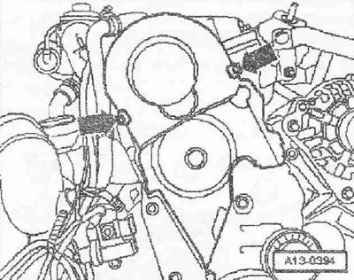
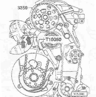
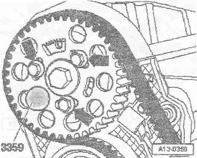
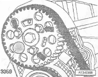
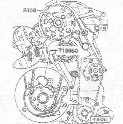
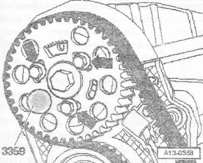
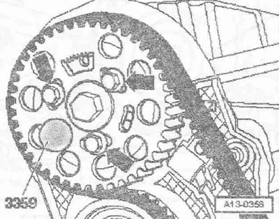
Set the crankshaft to the "TDC" mark. The gap between both teeth of the camshaft sprocket should be opposite the 3Z marking on the rear part of the belt guard "arrows". Fix the camshaft bushing with the "3359" lock. Fix the crankshaft sprocket with the "T10050" crankshaft stopper.
Instructions: The crankshaft stopper can only be pushed onto the sprocket teeth from the outside.
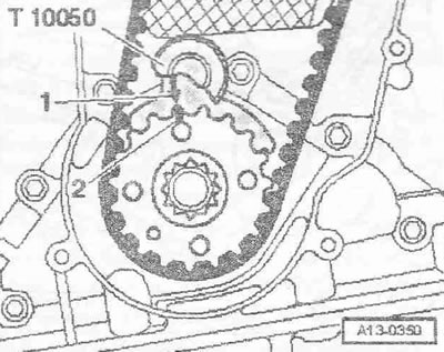
The markings on the sprocket and the crankshaft stopper "T10050" must be opposite each other. In this case, the journal of the crankshaft stopper "T10050" must enter the hole of the sealing flange.
Mark the direction of rotation of the timing belt with chalk or a felt-tip pen. Loosen the camshaft sprocket "arrow" bolts.
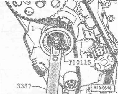
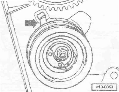
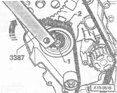
Loosen the tension roller fastening nut "1". Turn the tension roller eccentric with the trunnion key "3387" counterclockwise "arrow" so that it is possible to fix the tension roller with the lock "T10115". Instead of the trunnion key "3387", you can use the special tool Matra V/159.
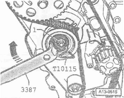
Turn the trunnion key "3387" clockwise "arrow" until it stops and tighten the fastening nut "1" by hand. Remove the toothed belt first from the coolant pump, and then from the remaining sprockets. Installation (valve timing adjustment). The camshaft is fixed with the lock "3359". The crankshaft is fixed with the crankshaft stop "T10050". The tension roller is fixed with the lock "T10115" and secured with the fastening nut to the right stop.
Instructions. Work on adjusting the timing belt must be carried out only when the engine is cold. When turning the camshaft, one of the crankshaft pistons must not be at "TDC". Risk of damage to valves/piston crown.
Check the correct fit of the tension roller in the rear part of the protective cover of the "stitch" belt.
Screw in the bolts "arrows" not all the way. The camshaft sprocket should turn with the force of your hand, but not turn on its own. Turn the camshaft sprocket clockwise until it stops within its extended holes. Install the toothed belt on the camshaft sprocket, tension roller, crankshaft sprocket and then on the coolant pump sprocket.
Adjust the position of the toothed belt tensioner as follows: Remove the lock "T10115". Loosen the fastening nut "1" of the tension roller. Turn the eccentric of the tension roller with the trunnion key "3387" clockwise "arrow" so that the pointer arrow "2" is in the middle in front of the recess of the base plate.
Instructions: Make sure that the fastening nut does not turn.
Fix the tension roller in this position and tighten the tension roller nut to a torque of 20 Nm at 45°.
Instructions. When tightening the fastening nut, the pointer turns a maximum of 5 mm to the right from the base plate recess. This position cannot be corrected, as the belt stretches after some time of operation.
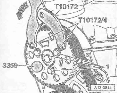
Install the support key "T10172" with the bolt "T10172/4" as shown in the figure and, pressing "in the direction of the arrow", create a preliminary tension on the leading branch of the belt. Tighten the bolts "1" of the camshaft sprocket with a torque of 25 Nm. Remove the lock "3359" and the crankshaft stopper "T10050".
Checking the valve timing
The engine may only be turned by the crankshaft in the direction of its rotation (clockwise). Turn the crankshaft 2 revolutions in the direction of rotation so that it is again in front of the "TDC" mark. Turn the sleeve in the direction of engine rotation, lock it with the "3359" lock. The gap between both teeth of the camshaft sprocket should be opposite the "3Z" marking on the rear part of the belt guard "arrows". For clarity, the camshaft sprocket is shown without a belt.
Check the following: the possibility of fixing the crankshaft with the crankshaft stopper "T10050", the location of the arrow of the tension roller pointer in the middle or maximum 5 mm to the right of the recess in the base plate. If the crankshaft cannot be fixed / loosen the fastening bolts "arrows" of the camshaft sprocket.
Turn the crankshaft in the direction of engine rotation so that it can be fixed with the crankshaft stopper "T10050".
Instructions: If the crankshaft has passed the "TDC" mark, first turn it back, and then re-set it to the "TDC" mark in the direction of engine rotation.
Tighten the camshaft sprocket "arrow" bolts with a torque of 25 Nm. Remove the "3359" retainer and the "T10050" crankshaft stopper. The engine may only be turned by the crankshaft in the direction of its rotation (clockwise).
Turn the crankshaft 2 revolutions in the direction of engine rotation until it is again at the "TDC" mark. Repeat the valve timing check.
Installation
Carried out in the reverse order, it is necessary that the hoses and hose nipple of the air boost system must be cleaned of oils and grease before installation. Do not use lubricants under any circumstances. Install the lower central part of the belt guard. Install the torsional vibration damper. Install the bracket together with the engine mount. Install the upper part of the belt guard. Install the air ducts in the clamps. Install the poly V-belt. Install the wiper arm.
Tightening torques:
- Camshaft sprocket to sleeve: 25 Nm
- Timing belt tension roller to cylinder head: 20 Nm + 45°
- Lower, part of the belt guard to the cylinder block: 10 Nm 1)
- Central part of the belt guard to the cylinder block: 10 Nm 1)
- Engine support to cylinder head: 45 Nm
- Poly V-belt tensioner to accessory bracket: 22 Nm
- Engine compartment cover to bracket: 5.5 Nm
1) Use thread sealant to tighten bolts.
[A link to the original source is available on the website AUDIMANUAL.RU]