
Note
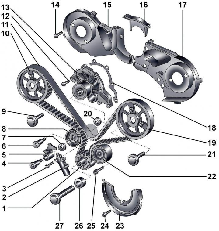
Pic. 3.3–32. Toothed belt: 1 - crankshaft pulley; 2 – toothed belt tensioner; 3 - bolt, 10 Nm; 4 - bolt, 42 Nm; 5 - lever of the tension mechanism; 6 - bolt, 42 Nm; 7 - washer; 8 - tension roller; 9 - bolt, 75 Nm; 10 – a pulley of a camshaft of inlet valves; 11 - toothed belt; 12 - bolt, 10 Nm; 13 - water pump; 14 - bolt, 10 Nm; 15 - right rear part of the casing; 16 - the central rear part of the casing; 17 - left rear part of the casing; 18 - gasket; 19 – a pulley of a camshaft of final valves; 20 - washer; 21 - bolt, 75 Nm; 22 - guide roller; 23 – a casing of a gear belt; 24 - bolt, 10 Nm; 25 - bolt, 45 Nm; 26 - bushing; 27 - bolt, 200 Nm + tighten by 180°
When installing, you must use a new gasket 18 (pic. 3.3–32) and bolt 27.
Withdrawal
Remove the oil filler cap.
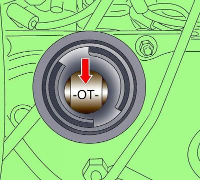
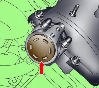
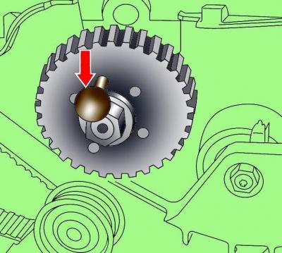
Pic. 3.3–33. The mark on the camshaft when installing the piston of the first cylinder at TDC of the compression stroke
For the pulley mounting bolt, turn the crankshaft in the direction of working rotation until the mark appears «OT» (TDC) on the camshaft in the oil filler hole (pic. 3.3–33).
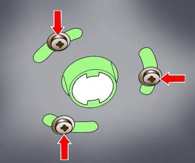
Pic. 3.3–34. Location of screws for fastening the exhaust pipe heater and noise insulation of the additional heater
Turn out screws of fastening of an exhaust pipe heater and a noise isolation of an additional heater (pic. 3.3–34).
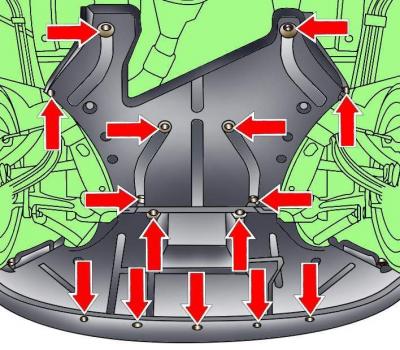
Pic. 3.3–35. The location of the fastening latches of the lower mudguard of the engine compartment
Release the clips and remove the front section of the lower mudguard of the engine compartment (pic. 3.3–35).
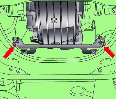
Pic. 3.3–36. Arrangement of bolts of fastening of an arm of the lower mudguard of a motor compartment
Unscrew the two bolts and remove the bracket for the lower mudguard of the engine compartment (pic. 3.3–36).
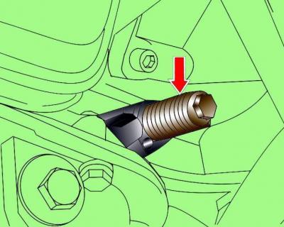
Pic. 3.3–37. Location of set screw 3242 to fix the crankshaft
Lock the crankshaft in this position. To do this, unscrew the plug from the cylinder block and screw in the set screw 3242 instead (pic. 3.3–37).
Remove the cover located behind the expansion tank.
Remove the vacuum hose from the vacuum pump.
Remove the vacuum pump mounting bolts and turn the pump counterclockwise.
Loosen the clamps and remove the air pipe from the air filter.
Disconnect the electrical connectors from the solenoid valve and EGR valve (EGR).
Disconnect the vacuum hoses from the turbocharger and mechanical EGR valve and move the hoses to the side.
Unscrew the bolts and remove the pipe connecting the turbocharger to the air cooler.
Pic. 3.3–38. The location of the cover that closes the end of the camshaft, on the right cylinder head
Using a screwdriver blade as a lever, remove the cover covering the end of the camshaft on the cylinder head (pic. 3.3–38).
Install camshaft position retainers 3458 instead of covers.
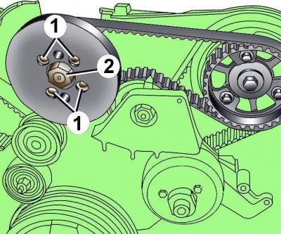
Pic. 3.3–39. Bolt location (1) vibration damper mountings and nuts (2) fuel pump pulley fasteners
Remove vibration damper from fuel pump pulley (pic. 3.3–39). Do not unscrew the nut 2 of the fuel pump pulley, otherwise the injection moment of the fuel pump will change.
Warning: Before removing with chalk, marker or paint, mark the direction of rotation of the toothed belt. If a used toothed belt rotates in the opposite direction when a used toothed belt is installed, it will break.
Loosen the fuel pump toothed belt tensioner and remove the belt.
Remove eight screws and remove vibration damper from the crankshaft pulley.
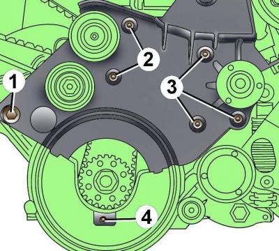
Pic. 3.3–40. Arrangement of bolts of fastening of a casing of a gear belt and an arm of the fan of a radiator: 1 – a bolt, 45 Н·м; 2 - bolts, 10 Nm; 3 - bolts, 22 Nm; 4 - bolt, 10 Nm
Unscrew a bolt of fastening of the bottom casing of a gear belt 4 (pic. 3.3–40).
Remove the viscous radiator fan pulley bolt.
Remove bolts 1-3 of the viscous radiator fan bracket and idler pulleys.
Unscrew bolts of fastening of a pulley of a gear belt from a pulley of the fuel pump.
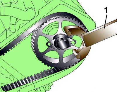
Pic. 3.3–41. Using Special Tool 3036 (1) for fixing the camshaft pulley from turning
Using special tool 3036 (pic. 3.3–41), secure the camshaft pulley against turning and loosen it one turn at a time (but do not unscrew completely) camshaft pulley bolts.
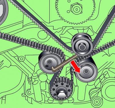
Pic. 3.3–42. Toothed belt loosening
Using an 8 mm socket wrench, turn the toothed belt tensioner clockwise and fix it with a 2 mm pin (pic. 3.3–42).
Pic. 3.3–43. Using the T40001 puller to remove the timing belt pulley from the camshaft
Using puller T40001 (pic. 3.3–43), remove both camshaft pulleys from the camshaft mounting cones. In this case, the puller must rest against the bolts of the camshaft pulleys. The camshaft pulleys must rotate freely, but not dangle on their mounting cones.
Unscrew a bolt and remove a pulley of a gear belt from the left head of the block of cylinders.
Remove the toothed belt.
Installation
Check that the position of the camshafts has been fixed with clamps 3458, and the crankshaft is in the TDC position of the first cylinder in the compression stroke.
The camshaft pulleys must turn freely.
You can install a toothed belt on both a cold and a warm engine.
There must be no grease between the pulley and the crankshaft.
Install the timing belt first on the crankshaft pulley, then on the right camshaft pulley, idler pulley, idler pulley and water pump pulley.
After that, install the toothed belt on the left camshaft pulley, then the pulley on the camshaft and secure it with a bolt.
Turn the toothed belt tensioner clockwise with an 8 mm socket wrench, remove the 2 mm diameter locking pin (see fig. 3.3–42) and release the key.
Pre-tension the toothed belt by turning the tension roller counterclockwise with an 8 mm socket wrench.
Using special tool 3036 (see fig. 3.3–41), fix the camshaft pulley from turning and alternately screw in the bolts of the camshaft pulley.
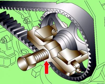
Pic. 3.3–44. Fixing pin 3359 fuel pump pulley
Fix the fuel pump pulley with pin 3359 (pic. 3.3–44).
Install the fuel pump drive pulley so that the bolts are in the middle of the elongated pulley holes, and tighten the bolts just enough to turn the fuel pump drive pulley on the camshaft pulley.
Install the fuel pump timing belt.
Adjust the tension of the fuel pump toothed belt by turning the tensioning mechanism counterclockwise with a hex wrench until the marks are aligned, and tighten the nut with the second wrench.
Remove clamps 3458 camshafts.
Remove pin 3359 that secures the fuel pump pulley.
Remove set screw 3242 that secures the crankshaft.
Remove set screw 3242 and retainers 3458, turn the crankshaft two full turns, set it to the TDC position of the first cylinder on the compression stroke, and check that the crankshaft and camshafts are correctly installed. To check the position of the crankshaft, unscrew the plug from the cylinder block and replace it with set screw 3242 (see fig. 3.3–37). To check the position of the camshafts, install clamps 3458 that fix the position of the camshafts. If set screw 3242 and retainers 3458 are seated, then the crankshaft and camshaft are installed correctly.
Notes
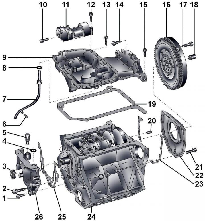
Pic. 3.3–46. Oil pan, engine front and rear covers: 1 - bolt M6, 10 Nm; 2 - bolt M8, 30 Nm; 3 – a sealing ring of a cranked shaft; 4 – O-ring; 5 - chain tensioner; 6 - bolt, 10 Nm; 7 – directing pipe of the index (probe) engine oil level; 8 – O-ring; 9 - the upper section of the oil pan; 10 - bolt, 45 Nm; 11 - casing; 12 - bolt, 22 Nm; 13 - M6 bolt to the cylinder block, 13 Nm; M6 to cover, 10 Nm; 14 - bolt, 45 Nm; 15 - M6 bolt to the cylinder block, 13 Nm; M6 to cover, 10 Nm; 16 – two-mass flywheel; 17 – a bolt of fastening of a flywheel; 18 - needle bearing; 19 - gasket; 20 - locating pin; 21 - bolt, 10 Nm; 22 - back cover with sealing ring; 23 - gasket; 24 - cylinder block; 25 - gasket; 26 - front cover
1. When installing, you must use new sealing rings 4, 8 (pic. 3.3–46) and gaskets 19, 23, 25.
2. The tightening torque of the flywheel mounting bolt 17 is 60 Nm + tighten by 180°, the friction lining bolts for vehicles with automatic transmission - 60 Nm + tighten by 90°. When installing it is necessary to use new bolts 17.
3. Needle bearing 18 is installed only on vehicles with a manual transmission and is pressed into the end of the crankshaft.
4. Gasket 19 during installation does not require the use of additional sealing agents.
5. When installing the sealing ring in the rear cover 22, it is necessary to lubricate its working edge with a thin layer of oil.
Install vibration damper on the fuel pump pulley and fasten it with bolts.
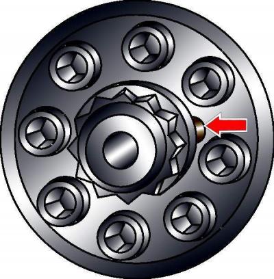
Pic. 3.3–45. The location of the mark on the vibration damper
Install the vibration damper on the crankshaft pulley, making sure that the mark (pic. 3.3–45) aligned with the mark on the toothed belt pulley, and tighten the vibration damper mounting bolts to 22 Nm.
Install a vacuum pump on the left cylinder head.
Further installation is carried out in the reverse order of removal.
Visitor comments