
Table of contents: Removal ↓ Installation ↓
Before you begin, please read the entire engine removal section carefully.
If the engine is removed for repair, it is necessary to select a place for the work, provide space for maintenance and storage of spare parts. Engine repairs should be carried out at a service station or in a garage with a level horizontal floor with a clean hard surface.
Before removing, clean and wash the engine and engine compartment. To remove the engine, use a lifting mechanism that allows you to safely lift the power unit.
If you are removing the engine for the first time, you should invite an experienced specialist. Some work is performed with an assistant.
All clamps and collars that are damaged or cut during engine removal must be replaced with new ones during engine assembly.
The engine is removed forward without the gearbox.
The drained coolant must be collected and disposed of.
Before disconnecting the battery, find out if you have a radio activation code.
Removal
Turn off the ignition and disconnect the ground wire from the battery.
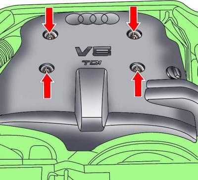
Fig. 3.3–24. Location of engine casing mounting screws
Loosen the screws and remove the engine casing (see Fig. 3.3–24).
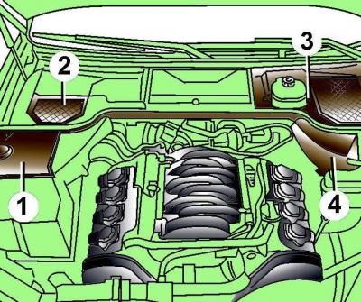
Fig. 3.3–1. Location of protective covers (1–4) in the rear of the engine compartment
Remove protective covers 1–4 at the rear of the engine compartment (Fig. 3.3–1).
Remove the expansion tank cap.
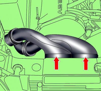
Fig. 3.3–25. Front air duct locations
Remove the front air ducts (see Fig. 3.3–25).
Loosen the radiator fan mounting bolt with a viscous coupling, holding the fan shaft from turning with another wrench.
Unscrew the radiator fan shroud.
Remove the viscous coupling fan together with the casing.
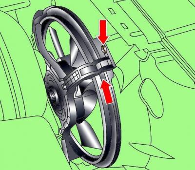
Fig. 3.3–2. Location of the shroud retainer and direction of rotation when removing the electric radiator fan
To remove the electric radiator fan, disconnect the electrical connector from the fan, remove the shroud retainer, turn the shroud in the direction of the arrow (Fig. 3.3–2), and remove the fan.
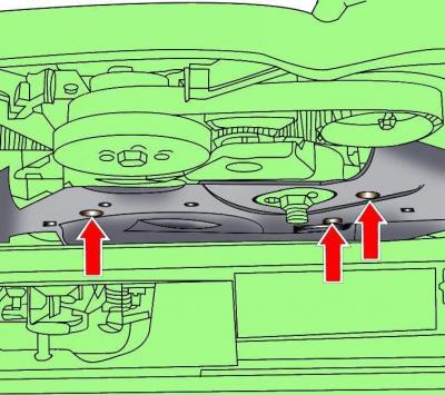
Fig. 3.3–27. Location of the poly V-belt cover mounting screws
Loosen the screws and remove the poly V-belt cover (see Fig. 3.3–27).
Warning: Using chalk, marker or paint, mark the direction of rotation of the poly V-belt. If the poly V-belt rotates in the wrong direction during installation, it will cause damage to the belt.
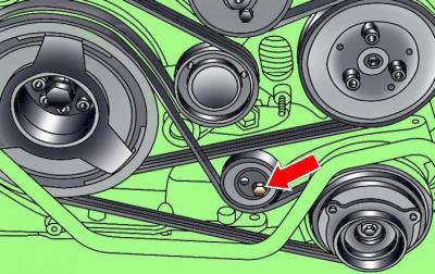
Fig. 3.3–28. Location of the bolt securing the tension roller of the poly V-belt of the air conditioner compressor
Loosen the tension roller mounting bolt of the air conditioner compressor poly V-belt and remove the belt from the pulleys (see Fig. 3.3–28).
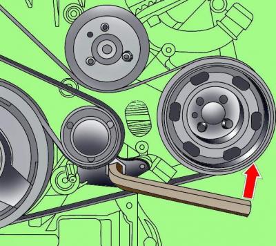
Fig. 3.3–29. Releasing the tension of the main poly V-belt
Using a socket wrench, turn the tensioning mechanism of the main poly V-belt counterclockwise, which will loosen the belt tension, fix the tensioning mechanism in this position with a pin (pos. 1, see Fig. 3.3–29) and remove the belt.
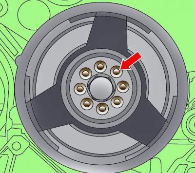
Fig. 3.3–3. Location of vibration damper mounting bolts
Remove the eight bolts and the vibration damper from the crankshaft pulley (Fig. 3.3–3).
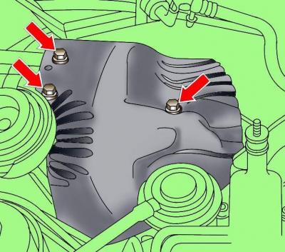
Fig. 3.3–4. Location of bolts securing the heat shield above the turbocharger
Remove the bolts (Fig. 3.3–4) and remove the heat shield above the turbocharger.
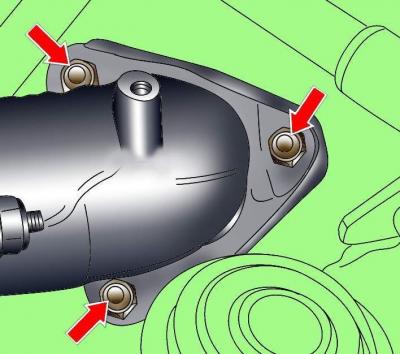
Fig. 3.3–5. Location of bolts securing the exhaust inlet pipe to the turbocharger
Remove the bolts securing the exhaust inlet pipe to the turbocharger (Fig. 3.3–5).
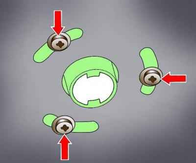
Fig. 3.3–34. Location of the exhaust pipe heater mounting screws and additional heater sound insulation
Remove the screws securing the exhaust pipe heater and the additional heater sound insulation (see Fig. 3.3–34).
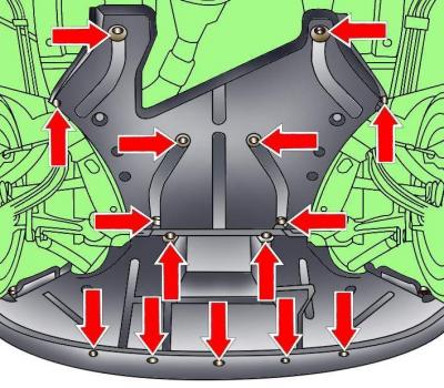
Fig. 3.3–35. Location of engine compartment lower mudguard mounting fasteners
Release the fasteners and remove the lower engine compartment mudguards, which consist of two sections (see Fig. 3.3–35).
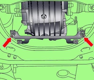
Fig. 3.3–36. Location of engine compartment lower mudguard bracket mounting bolts
Remove the two bolts and the engine compartment lower mudguard bracket (see Fig. 3.3–36)
Loosen the clamps and remove the front exhaust pipe with the catalytic converter.
Place a coolant collection pan under the engine.
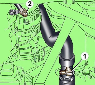
Fig. 3.3–6. Location of coolant drain cock (1) and drain bolt (2)
Drain the coolant by turning tap 1 (Fig. 3.3–6) at the base of the pipe by 90° and unscrewing drain bolt 2.
Unscrew the air conditioning compressor from the bracket and, without disconnecting the hoses from it, move it to the side.
Remove the torque compensator from the engine and body.
Unscrew the elastic support at the bottom right of the frame.
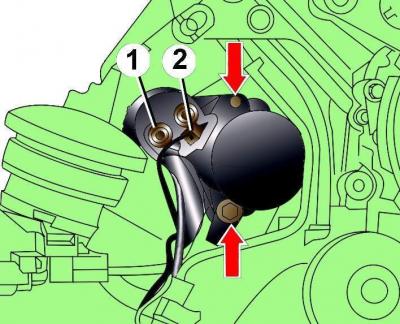
Fig. 3.3–7. Location of starter mounting bolts: 1 – nut; 2 – electrical connector
Disconnect the electrical connector from the starter, then unscrew nut 1 (Fig. 3.3–7) and disconnect the positive wire from the starter.
Unscrew the two bolts shown by the arrows in Fig. 3.3–7 and carefully remove the starter.
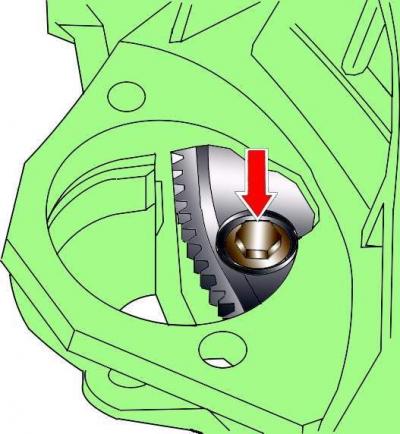
Fig. 3.3–8. Location of torque converter mounting bolt
Through the hole that opens after removing the starter, unscrew the three torque converter mounting bolts (Fig. 3.3–8). To access each subsequent bolt, it is necessary to turn the engine crankshaft in the direction of its working rotation by 1/3 of a turn.
Note: To turn the crankshaft, it is necessary to use the crankshaft pulley mounting bolt.
Cars with manual transmission
Unscrew and remove the cover from the right side of the drive shaft.
In the right distribution block, disconnect the electrical connector and, having unscrewed the nut, remove the tip of the starter wire. Then unscrew the bolt of the wire clamp and move the starter wire to the side.
Disconnect the electrical connector from the reverse light switch.
All models
Unscrew and remove the cover from the left drive shaft side.
Remove the heat shield from the left side of the gearbox.
Disconnect the electrical connector from the speedometer sensor.
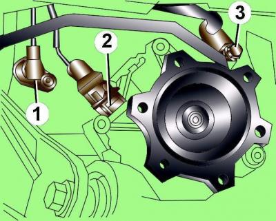
Fig. 3.3–9. Location of electrical connector (1), speedometer sensor, engine speed sensor (2) and automatic transmission pipe mounting bolt (3)
If there is sensor 2 (Fig. 3.3–9) engine speed G28, unscrew it. Sensor 2 is located in the front left part of the gearbox.
Unscrew bolt 3 of the automatic transmission pipeline and move the pipeline to the side.
Release and disconnect the wiring harness and multifunction switch electrical connectors from the bracket.
Disconnect the electrical connectors on the left side of the engine.
Remove the lower gearbox-to-engine mounting bolts.
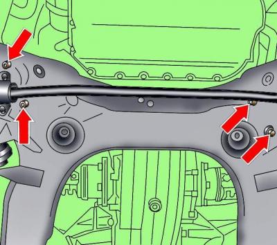
Fig. 3.3–10. Location of bolts (arrows) for fastening the engine to the lower frame
Unscrew the lower bolts, shown by arrows in Fig. 3.3–10, securing the engine to the lower frame.
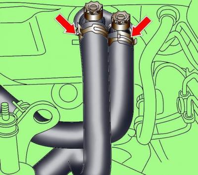
Fig. 3.3–11. Location of the clamps for fastening the cooling system hoses to the heater fittings on the engine compartment bulkhead
Loosen the clamps (Fig. 3.3–11) and disconnect the cooling system hoses going to the heater.
Remove the vacuum hose from the brake booster.
Loosen the clamps and disconnect the cooling system hoses from the engine.
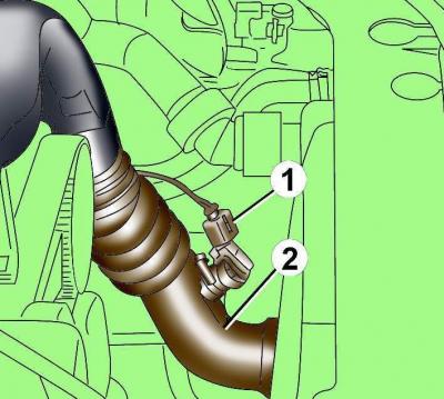
Fig. 3.3–12. Location of the sensor electrical connector (1) in the air supply hose (2) to the intake manifold
Disconnect the electrical connector from the air duct sensor 1 (Fig. 3.3–12).
Remove the air supply hose 2 to the intake manifold.
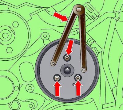
Fig. 3.3–21. Location of the power steering pump poly V-belt pulley mounting bolts and a special tool to prevent the pulley from turning
Unscrew the bolts securing the power steering pump poly V-belt pulley, holding the pulley from turning with a special tool (see Fig. 3.3–21).
Loosen the clamps and remove the air duct from the air filter.
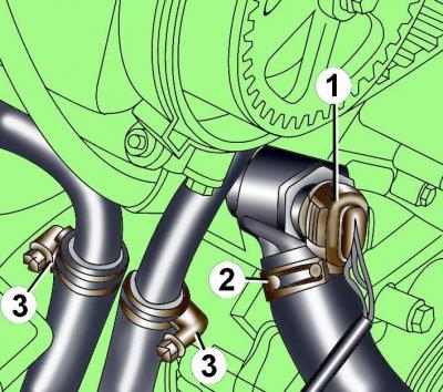
Fig. 3.3–13. Location of the electrical connector (1) of the radiator fan sensor and the clamps for fastening the cooling system hoses from the sensor (2) and the auxiliary heater (3)
Disconnect electrical connector 1 and cooling system hose from sensor 2 (Fig. 3.3–13) of the cooling system fan.
Loosen the clamps and disconnect the cooling system hoses from the auxiliary heater 3.
Disconnect the fuel hoses from the fuel filter.
Remove the air filter cover.
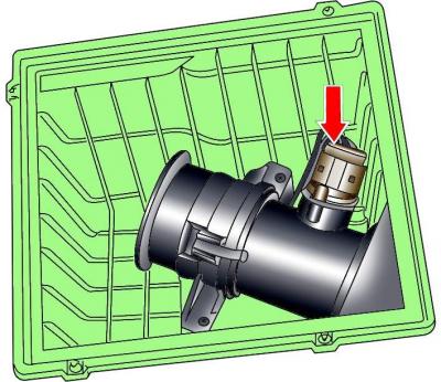
Fig. 3.3–14. Location of the air flow meter electrical connector
Disconnect the electrical connector from the air flow meter (Fig. 3.3–14) and release the wires from the clips.
Disconnect the electrical connectors from the solenoid valve and the exhaust gas recirculation (EGR) valve.
Disconnect the vacuum hoses from the turbocharger and mechanical EGR valve and move the hoses to the side.
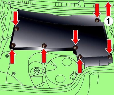
Fig. 3.3–15. Location of screws and direction of removal of the control unit casing: 1 – direction of removal
Turn the left protective cover of the control unit in the direction of arrow 1 (Fig. 3.3–15) and unscrew the rear right screw.
Remove the remaining mounting screws shown by the arrows in Fig. 3.3–15.
Remove the control unit cover.
In the control unit, disconnect the electrical connectors from the engine and gearbox control units. Release the relay mount by using a thin-bladed screwdriver to press the side clips.
Disconnect the remaining connectors and remove the wiring harness from the top of the engine.
Remove the upper transmission-to-engine mounting bolts, leaving one bolt in place.
Loosen the bolt on the back of the turbocharger.
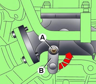
Fig. 3.3–16. Location of bolt (A) for mounting strut (B) on rear of turbocharger
A (Fig. 3.3–16), turn the stand clockwise and tighten the bolt again.
Disconnect the hood support struts from the hood. Position the hood vertically and secure it in this position.
Attach the 2024 lifting clamp to the hoist and secure its clamps to the engine.
Unscrew the bolts securing the gearbox to the engine.
Check that all electrical wires, hoses, pipes and lines are disconnected from the engine.
Cars with automatic transmission
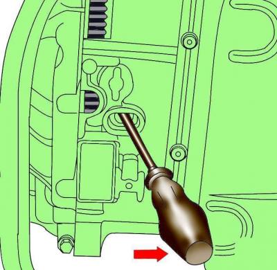
Fig. 3.3–17. Using a large screwdriver to press the torque converter against the engine when removing the engine
Before removing the engine, use a large screwdriver to press the torque converter against the engine (Fig. 3.3–17).
Carefully lift the engine, then move it away from the transmission and lift it up out of the engine bay.
Cars with automatic transmission
Secure the torque converter to the engine.
Installation
Installation is carried out in the reverse order of removal, taking into account the following.
When installing the engine, it is necessary to replace the self-locking nuts and bolts, which were tightened by turning them to a certain angle, with new ones, as well as the sealing rings and gaskets.
Before installation, make sure the rack IN (see Fig. 3.3–16) on the rear of the turbocharger is turned clockwise.
Before installing the engine, secure electrical wires and hoses to the sides of the engine compartment to prevent them from being pinched by the engine.
When installing, check for the presence of centering bushings that determine the relative position of the engine and gearbox.
Cars with manual transmission
Clean the splines of the drive shaft and remove any traces of corrosion from the clutch disc when reusing it. Lubricate the splines of the drive shaft with a thin layer of G 000 100 grease.
Check the condition of the clutch release bearing and replace it if necessary.
Using a drift, check the centering of the clutch disc.
Check the condition of the needle bearing at the flywheel end of the crankshaft. Replace the bearing if necessary.
Cars with automatic transmission
To attach the torque converter to the flywheel, it is necessary to use bolts of the original design.
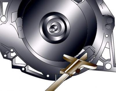
Fig. 3.3–18. Measuring the distance between the bearing surface for the torque converter mounting bolts and the bearing surface of the crankcase
Check the correct installation of the torque converter. If the distance between the supporting surface for the torque converter mounting bolts and the housing surface is 19 mm, then the torque converter is installed correctly. If the torque converter is installed incorrectly, this distance is about 14 mm (Fig. 3.3–18). In this case, the torque converter drive disk and the automatic transmission pump are destroyed.
Place the engine in place and rock it from side to side to ensure it is correctly positioned on the supports.
Install the air conditioning compressor and power steering pump.
Before tightening the A/C compressor mounting bolts, make sure the compressor centering bushings are in place.
Install power steering pump pulley.
Install the poly V-belt.
Install the radiator fan with viscous coupling.
Install the torque compensator and bolt it to the engine and body.
Fill the cooling system with coolant. Do not reuse coolant if the cylinder head has been removed or the cylinder block has been replaced.
Check that the exhaust system components are correctly mounted on the suspensions and do not touch the body when it is rocking.
Check that the electrical connectors are connected correctly.
Connect the ground wire to the battery.
Turn on radio and enter the code into it.
Raise the power windows all the way up. Then press all power window switches again for at least 1 second to the closed position to activate the power window control unit.
Set the time on the clock.
Before starting the engine for the first time, it is necessary to bleed the fuel system, otherwise the fuel pump will be damaged.
Before starting the engine, check the presence and level of oil in the engine.