
If the crankshaft has been ground, check for burrs around the oil holes. Remove any burrs found with a needle file or scraper and carefully clean the holes and channels from chips.
Using a micrometer, measure the diameter of the main and connecting rod journals of the crankshaft and compare the results with the technical data. Necks are measured at several points both in diameter and length, this will reveal ovality and taper, if any.
Check the oil seal contact surfaces at each end of the crankshaft for wear or other damage. If the journal is severely worn from the seal, then the crankshaft may need to be replaced.
Wear of the connecting rod journal is characterized by metallic knocks during engine operation, especially under load, at low speeds, and a decrease in oil pressure.
Wear of the crankshaft journals is characterized by strong engine vibration and a metallic sound that increases with increasing engine speed, as well as a decrease in oil pressure.
Even if the main and connecting rod bearings are to be replaced during the overhaul of the engine, they must be carefully examined: their defects can be used to judge the technical condition of the engine.
The bearing can fail due to lack of lubrication, contamination, foreign particles, motor overload or corrosion. The cause of the bearing failure must be corrected before the engine is reassembled.
To inspect the bearings, remove and arrange them in the same order in which they were installed on the engine. This will identify the appropriate crankshaft journal and facilitate troubleshooting.
Foreign particles can enter the engine in various ways. Metal particles appear in engine oil as a result of normal engine wear. Small particles along with the oil can get into the bearings and easily penetrate into their soft material. Larger particles can scratch the bearing or crankshaft journal. To prevent bearing failure from this cause, thoroughly clean all internal surfaces of the motor and keep them clean when reassembling the motor. It is also recommended that the required oil and filter change intervals be observed.
Insufficient lubrication of the crankshaft journals can be caused by many reasons: high oil temperature, engine overload, oil leakage, etc.
The way you drive your car also has an impact on bearing life. When the throttle is fully open at a low engine speed, the load on the bearings increases and the oil film is squeezed out of the contact zone. High loads lead to the appearance of cracks in the working part of the bearing, which in turn can cause the anti-friction layer to separate from the steel base.
Short distance driving results in corrosion of the bearings as a result of the motor not reaching a stabilized operating temperature that removes water vapor and corrosive gases. Condensing in engine oil, they form acid and sludge. Acid, along with engine oil, gets into the bearings and causes corrosion.
Incorrect selection of bearings during engine assembly also causes bearing failure. Preloaded bearings leave insufficient clearance to ensure proper lubrication.
When installing the crankshaft, consider the following.
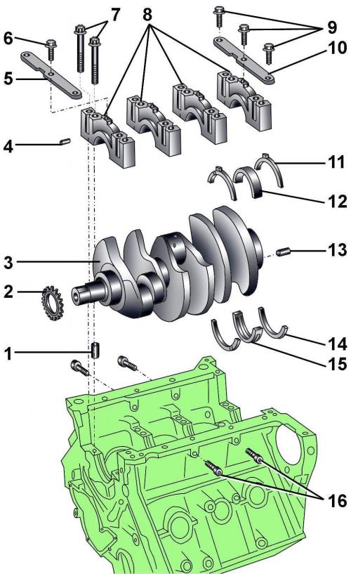
Pic. 3.3–47. Crankshaft: 1 - centering sleeve; 2 - chain sprocket; 3 - crankshaft; 4 - locating pin; 5 - rack; 6 - bolt, 22 Nm; 7 – bolts of fastening of covers of bearings; 8 - bearing cover; 9 - bolt, 22 Nm; 10 - rack; 11 - persistent half ring; 12 – insert of the main bearing; 13 - pin; 14 - persistent half ring; 15 – insert of the main bearing; 16 - bolts
Thrust half rings 11 and 14 (pic. 3.3–47) are installed only on the fourth main bearing and are used to adjust the axial clearance of the crankshaft.
The lubrication grooves of the thrust half rings must be directed outward.
Insert 12 without oil groove is installed on the side of the bearing cover.
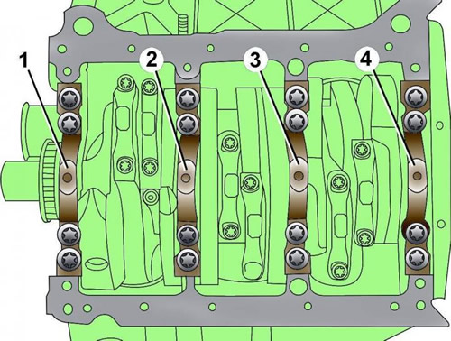
Pic. 3.3–48. Location and numbering of crankshaft main bearings
Main bearing #1 is on the pulley side and bearing #4 is on the flywheel side (pic. 3.3–48).
At installation it is necessary to use new bolts of fastening of covers of bearings.
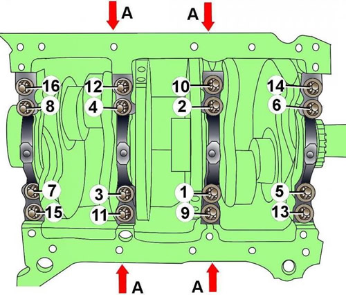
Pic. 3.3–49. The sequence of tightening the bolts of the main bearing caps
Bolts of fastening of covers of radical bearings tighten in the sequence shown in drawing 3.3–49, in five stages:
- 1st - tighten bolts 1–8 to 60 Nm;
- 2nd - tighten bolts 1–8 at an angle of 90°;
- 3rd - tighten bolts 9–16 to 60 Nm;
- 4th - tighten bolts 9–16 at an angle of 90°;
- 5th - tighten the bolts A torque 28 Nm
Measurement of axial and radial clearances of the crankshaft
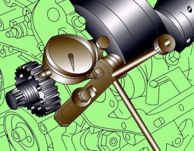
Pic. 3.3–50. Installation of a bracket with a dial indicator for measuring the axial clearance of the crankshaft
Install the bracket with the dial indicator on the engine block so that the measuring tip of the indicator rests against the counterweight of the crankshaft (pic. 3.3–50).
Move the crankshaft along the axis to one side until it stops and set the dial indicator to 0. Move the crankshaft along the axis to the other side until it stops and fix the value shown by the indicator. The nominal value of the axial clearance of the crankshaft is 0.090–0.251 mm, the maximum allowable value is 0.30 mm.
To measure the radial clearance in the crankshaft bearings, a calibrated Plastigage plastic rod must be used.
Unscrew the bolts and remove the main bearing cap and main bearing. Clean the bearing, cover and crankshaft journal.
Cut off a piece of plastic calibrated rod, the length of which is equal to the width of the bearing, and lay it along the axis of the crankshaft on the main bearing journal.
Install the bearing cover with the bushing and fix it with bolts, tightening them with a torque of 30 Nm. Do not turn the crankshaft while doing this.
Unscrew the bolts and remove the main bearing cap again. Compare the width of the deformed plastic rod with the measuring scale printed on the packaging of the plastic rod. On the scale, determine the radial clearance. The nominal value of the radial clearance of the crankshaft is 0.018–0.045 mm, the maximum allowable value is 0.10 mm.
Visitor comments