
Front intake manifold
Turn off the ignition and disconnect the wire «masses» from the battery.
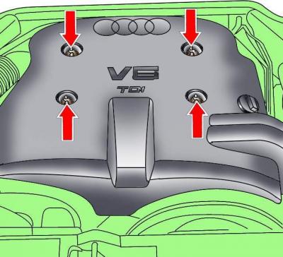
Pic. 3.3–24. Location of engine cover screws
Loosen the screws and remove the engine cover (see fig. 3.3–24).
Disconnect the flap control vacuum hose, if equipped.
Disconnect the air intake hose from the flap and move the hoses to the side.
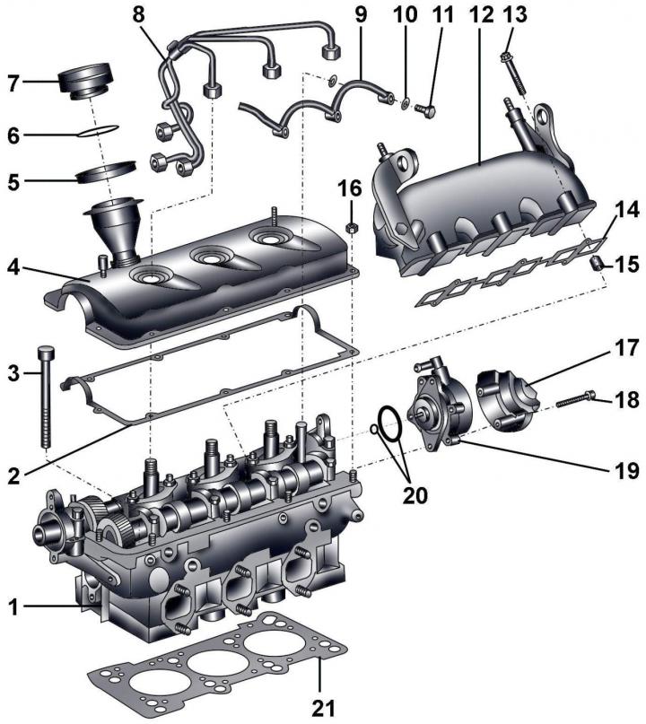
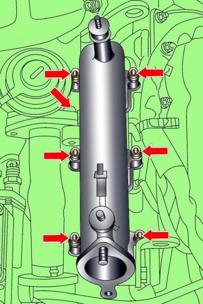
Pic. 3.3–51. Cylinder head: 1 – a head of the block of cylinders; 2 – a lining of a cover of a head of the block of cylinders; 3 – bolts of fastening of a head of the block of cylinders; 4 – a cover of a head of the block of cylinders; 5 - oil flinger ring; 6 - gasket; 7 - cover; 8 – fuel tubes of injectors; 9 - fuel return pipes; 10 - sealing ring; 11 - hollow bolt, 5 Nm; 12 - intake manifold; 13 - bolt, 10 Nm; 14 - gasket; 15 - centering sleeve; 16 - nut, 10 Nm; 17 - heat shield of the vacuum pump; 18 - bolt; 19 - vacuum pump, 10 Nm; 20 - sealing rings; 21 – a lining of a head of the block of cylinders
Pic. 3.3–52. Arrangement of bolts of fastening of forward section of an inlet collector
Unscrew the bolts and remove the front section of the intake manifold (pic. 3.3–52).
Installation is carried out in the reverse order of removal.
Left section of the intake manifold
Remove the front section of the intake manifold.
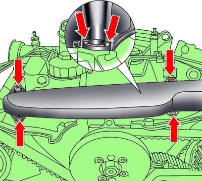
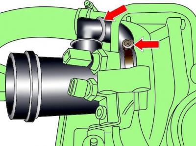
Pic. 3.3–4. The location of the bolts for securing the heat shield above the turbocharger
Unscrew the bolts and remove the heat shield above the turbocharger (see fig. 3.3–4).
Mark and disconnect the fuel lines from the injectors.
Loosen and move aside the wiring harness from the left section of the intake manifold.
Pic. 3.3–53. Arrangement of bolts of fastening of the left section of an inlet collector
Unscrew the bolts and remove the left section of the intake manifold (pic. 3.3–53).
Installation is carried out in the reverse order of removal.
Right intake manifold section
Remove the front section of the intake manifold.
Disconnect the vacuum hoses from the turbocharger and mechanical EGR valves and move the hoses to the side.
Mark and disconnect the fuel lines from the injectors.
Release the fuel lines and move them away from the right section of the intake manifold.
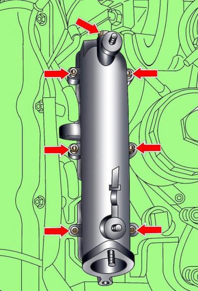
Pic. 3.3–54. Arrangement of bolts of fastening of the right section of an inlet collector
Turn out bolts and remove the right section of an inlet collector (pic. 3.3–54).
Installation is carried out in the reverse order of removal.
Left cylinder head cover
Remove the front section of the intake manifold.
Loosen and move aside the wiring harness from the left cylinder head cover.
Mark and disconnect the fuel lines from the injectors.
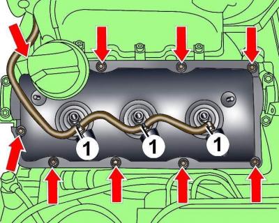
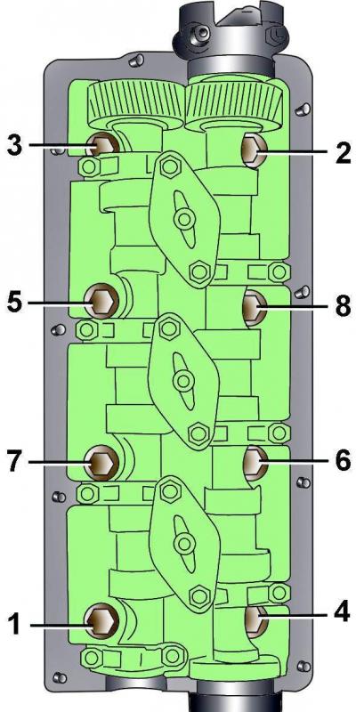
Pic. 3.3–55. Arrangement of nuts of fastening of the left cover of a head of the block of cylinders and a tube (1) fuel return
Unscrew the hollow bolts and remove the fuel return pipes 1 (pic. 3.3–55) from nozzles.
Unscrew nuts and remove the left cover of a head of the block of cylinders.
Installation is carried out in the reverse order of removal, taking into account the following.
Replace O-rings on fuel return pipes.
Replace damaged cylinder head cover gasket.
If the fuel injector O-rings are damaged, the cylinder head cover must be replaced.
Degrease the surface mating with the cylinder head cover gasket.
Pic. 3.3–56. Places for applying sealant before installing the cylinder head cover
Apply a thin, continuous layer of sealant to the semi-circular surface (pic. 3.3–56) at the end of the cylinder head.
Apply a 3 mm diameter layer of sealant in 5 mm projection lengths to the outer camshaft covers (see fig. 3.3–56).
Tighten nuts of fastening of a cover of a head of the block of cylinders gradually and crosswise.
Connect fuel pipes.
Install the front section of the intake manifold.
Right cylinder head cover
Warning: All clips and clamps that are damaged or cut when the cylinder head cover is removed must be replaced with new ones when the cylinder head cover is installed.
Loosen the screws and remove the engine cover (see fig. 3.3–24).
Loosen the clamps and remove the air pipe from the air filter.
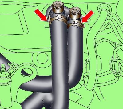
Pic. 3.3–57. Fastening pipes to the turbocharger
Loosen and remove pipes from turbocharger (pic. 3.3–57).
Mark and disconnect the fuel lines from the injectors.
Loosen and move aside the wiring harness from the right cylinder head cover.
Unscrew the bolts and remove the pipe connecting the turbocharger to the air cooler.
Unscrew the bolt securing the pipe for the dipstick of the engine oil level.
Unscrew the hollow bolts and remove the fuel return pipes.
Unscrew nuts and remove a cover of a head of the block of cylinders.
Installation is carried out in the reverse order of removal, taking into account the following.
Replace O-rings on fuel return pipes.
Replace damaged cylinder head cover gasket.
If the fuel injector O-rings are damaged, the cylinder head cover must be replaced.
Degrease the surface mating with the cylinder head cover gasket.
Apply a thin, continuous layer of sealant to the semi-circular surface (see fig. 48) at the end of the cylinder head.
Apply a 3 mm diameter layer of sealant in 5 mm projection lengths to the outer camshaft covers (see fig. 3.3–56).
Tighten nuts of fastening of a cover of a head of the block of cylinders gradually and crosswise.
Connect fuel pipes.
Left cylinder head
Warning: All clips and clamps that will be damaged or cut when the cylinder head cover is removed must be replaced with new ones when the cylinder head is installed.
Before disconnecting the battery, find out if you have a radio activation code.
Turn off the ignition and disconnect the wire «masses» from the battery.
Drain the coolant from the cooling system.
Remove the toothed belt from the camshaft pulleys.
Remove the front section of the intake manifold.
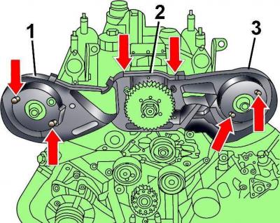
Pic. 3.3–58. The location of the screws for fixing the left (1), top (2) and right (3) toothed belt covers
Turn away screws and remove the top section of a casing of a gear belt 2 (pic. 3.3–58).
Turn away screws and remove left 1 and right 3 casings of a gear belt.
Loosen the clamps, unscrew the three bolts and remove the cooling system hoses from the front of the engine.
Disconnect electrical wires from glow plugs.
Turn out a bolt of fastening of the valve of recirculation of the fulfilled gases to the left section of an inlet manifold.
Loosen and move aside the wiring harness from the left cylinder head.
Pic. 3.3–11. Location of the clamps for fastening the cooling system hoses to the heater fittings on the bulkhead of the engine compartment
Loosen the clamps (see fig. 3.3–11) and disconnect the coolant hoses going to the heater.
Loosen the clamps and disconnect the hoses from the cooling system pipe, and unscrew the pipe mounting bolt.
Mark and disconnect the fuel lines from the injectors.
Unscrew the hollow bolts and remove the fuel return pipes from the injectors 1 (see fig. 3.3–55).
Unscrew nuts and remove a cover of a head of the block of cylinders.
Pic. 3.3–59. Cylinder head bolt tightening sequence
In the reverse order to tightening, gradually loosen and then completely unscrew the cylinder head bolts (pic. 3.3–59).
Remove the cylinder head and place it on a soft base.
Right cylinder head
Warning: All clips and clamps that will be damaged or cut when the cylinder head is removed must be replaced with new ones when the cylinder head is installed.
Before disconnecting the battery, find out if you have a radio activation code.
Turn off the ignition and disconnect the wire «masses» from the battery.
Drain the coolant from the cooling system.
Remove the right exhaust manifold together with the front exhaust pipe.
Remove the toothed belt from the camshaft pulleys.
Remove the front section of the intake manifold.
Loosen and remove pipes from turbocharger (see fig. 3.3–57).
Unscrew the bolts and move the air filter cover to the side without disconnecting the hoses from it.
Remove the air filter housing.
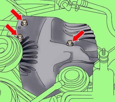
Unscrew the bolts and remove the heat shield above the turbocharger (see fig. 3.3–4).
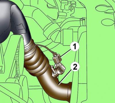
Pic. 3.3–12. Sensor electrical connector location (1) in the hose (2) air supply to intake manifold
Disconnect the electrical connector from the air inlet sensor 1 (see fig. 3.3–12).
Remove the air supply hose 2 to the intake manifold.
Pic. 3.3–60. Fastening the oil supply pipe to the turbocharger and intake manifold
Disconnect the oil supply pipe from the turbocharger (pic. 3.3–60).
Disconnect the oil supply pipe from the intake manifold (see fig. 3.3–60).
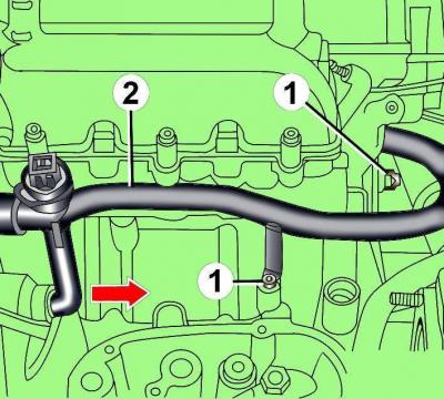
Pic. 3.3–61. Bolt location (1) pipe fastening (2) cooling system and direction of its movement
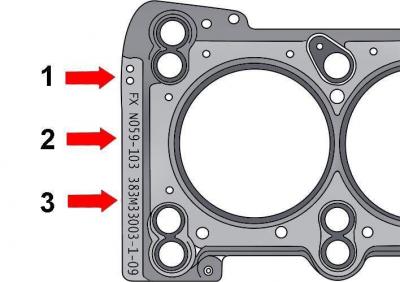
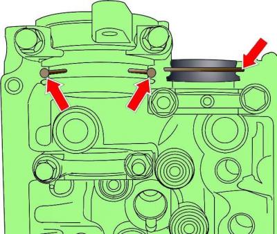
Pic. 3.3–62. Marking the cylinder head cover gasket with holes (1), number (2) and production code (3)
Unscrew the two bolts securing the cooling pipe, move it to the rear of the engine and leave it in this position (pic. 3.3–61).
Unscrew a bolt of fastening of the right pipe of system of cooling to an intermediate ledge, without separating a pipe.
Unscrew bolts of fastening of the right pipe of system of cooling to a head of the block of cylinders.
Unscrew bolts and remove the top casing of a gear belt.
Remove right intake manifold.
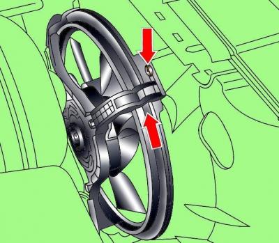
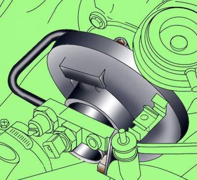
Pic. 3.3–2. Shroud retainer location and direction of rotation when removing the electric radiator fan
To remove the electrically driven radiator fan, disconnect the electrical connector from the fan, remove the shroud retainer, then turn the shroud counterclockwise (see fig. 3.3–2) and remove the fan.
Unscrew the generator mounting bolts, but do not disconnect the wires from it.
Unscrew the pipe mounting bolt for the pointer (probe) engine oil level.
Unscrew the hollow bolts and remove the fuel return pipes 1 (see fig. 3.3–55) from nozzles.
In the reverse order to tightening, gradually loosen and then completely unscrew the cylinder head bolts (see fig. 3.3–59).
Remove the cylinder head and place it on a soft base.
Preparing the head for installation
The mating surfaces of the head and cylinder block must be perfectly clean. Use a hard plastic or wooden scraper to clean them. Be careful when cleaning as aluminum alloy is very easy to damage. Make sure that carbon deposits do not get into the oil and water channels. This is especially important for the lubrication system, as deposits can block the oil supply to engine parts. Clean channels if necessary.
Check the mating surfaces of the cylinder head and block for nicks, deep scratches and other damage. Small defects can be removed by machining. In case of significant defects, the parts must be replaced.
Check the flatness of the mating surface of the cylinder head.
Clean the bolt holes in the block. Screwing a bolt into an oil-filled hole may rupture the block due to increased hydraulic pressure.
Installing the cylinder head
Installation is carried out in the reverse order of removal, taking into account the following.
When installing the cylinder head, it is necessary to replace it with new self-locking nuts and bolts, which were tightened by tightening to a certain angle, as well as sealing rings and gaskets.
A new cylinder head gasket must be removed from the packaging immediately before installation.
If new pistons are installed on the engine, it is necessary to measure the protrusion of the pistons from the cylinder block and, in accordance with this value, select the thickness of the new cylinder head gasket (pic. 3.3–59).
| Protrusion of pistons, mm | Number of holes |
| 0,39–0,49 | 1 |
| 0,49–0,54 | 2 |
| 0,54–0,65 | 3 |
Install the gasket on the guide pins, while the inscription «oben» should point towards the head.
If work has been done on the valve train, turn the engine two full turns by hand to make sure the pistons do not hit the valves.
Pic. 3.3–37. Location of set screw 3242 to fix the crankshaft
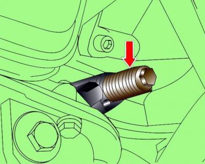
Before installing the cylinder head, set the piston of the first cylinder and the camshaft to TDC on the compression stroke. Lock the crankshaft in this position by unscrewing the fuel injection timing sensor from the cylinder block and screwing in set screw 3242 instead (see fig. 3.3–37).
Insert the cylinder head bolts and tighten them by hand, and then in the sequence shown in Figure 3.3-59, in four steps:
- 1st - 35 Nm;
- 2nd - 60 Nm;
- 3rd - tighten by an angle of 90°;
- 4th - tighten by an angle of 90°.
In the future, additional tightening of the cylinder head bolts is not required.
Install the cylinder head cover.
When installing the guide tube for the pointer (probe) engine oil level, a new O-ring must be installed.
Install the toothed belt.
Install the exhaust manifold.
Install poly V-belt.
Fill with fresh coolant.
Remove air from the fuel supply system.
Connect wire «masses» to the battery.
Turn on radio and enter the code into it.
Raise the windows with the power windows up to the stop. Then press all power window switches again for at least 1 second to the closed position to activate the power window control unit.
Set the time on the clock.
Visitor comments